System Management Feature Specifications
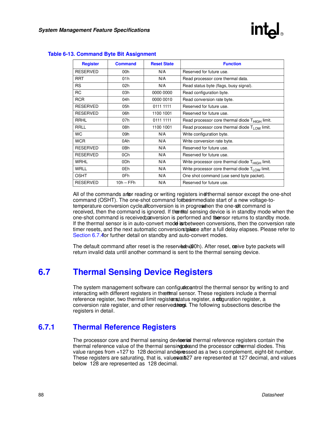
Table 6-13. Command Byte Bit Assignment
Register | Command | Reset State | Function |
|
|
|
|
RESERVED | 00h | N/A | Reserved for future use. |
|
|
|
|
RRT | 01h | N/A | Read processor core thermal data. |
|
|
|
|
RS | 02h | N/A | Read status byte (flags, busy signal). |
|
|
|
|
RC | 03h | 0000 0000 | Read configuration byte. |
|
|
|
|
RCR | 04h | 0000 0010 | Read conversion rate byte. |
|
|
|
|
RESERVED | 05h | 0111 1111 | Reserved for future use. |
|
|
|
|
RESERVED | 06h | 1100 1001 | Reserved for future use. |
|
|
|
|
RRHL | 07h | 0111 1111 | Read processor core thermal diode THIGH limit. |
RRLL | 08h | 1100 1001 | Read processor core thermal diode TLOW limit. |
WC | 09h | N/A | Write configuration byte. |
|
|
|
|
WCR | 0Ah | N/A | Write conversion rate byte. |
|
|
|
|
RESERVED | 0Bh | N/A | Reserved for future use. |
|
|
|
|
RESERVED | 0Ch | N/A | Reserved for future use. |
|
|
|
|
WRHL | 0Dh | N/A | Write processor core thermal diode THIGH limit. |
WRLL | 0Eh | N/A | Write processor core thermal diode TLOW limit. |
OSHT | 0Fh | N/A | One shot command (use send byte packet). |
|
|
|
|
RESERVED | 10h – FFh | N/A | Reserved for future use. |
|
|
|
|
All of the commands are for reading or writing registers in the thermal sensor except the
The default command after reset is the reserved value (00h). After reset, receive byte packets will return invalid data until another command is sent to the thermal sensing device.
6.7Thermal Sensing Device Registers
The system management software can configure and control the thermal sensor by writing to and interacting with different registers in the thermal sensor. These registers include a thermal reference register, two thermal limit registers, a status register, a configuration register, a conversion rate register, and other reserved registers. The following subsections describe the registers in detail.
6.7.1Thermal Reference Registers
The processor core and thermal sensing device internal thermal reference registers contain the thermal reference value of the thermal sensing device and the processor core thermal diodes. This value ranges from +127 to
88 | Datasheet |