System Management Feature Specifications
6.7.2Thermal Limit Registers
The thermal sensing device has two thermal limit registers; they define high and low limits for the processor core thermal diode. The encoding for these registers is the same as for the thermal reference registers. If the diode thermal value equals or exceeds one of its limits, then its alarm bit in the status register is triggered. This indication is also brought out to the Itanium 2 processor system bus via the THRMALERT# signal.
6.7.3Status Register
The status register shown in Table
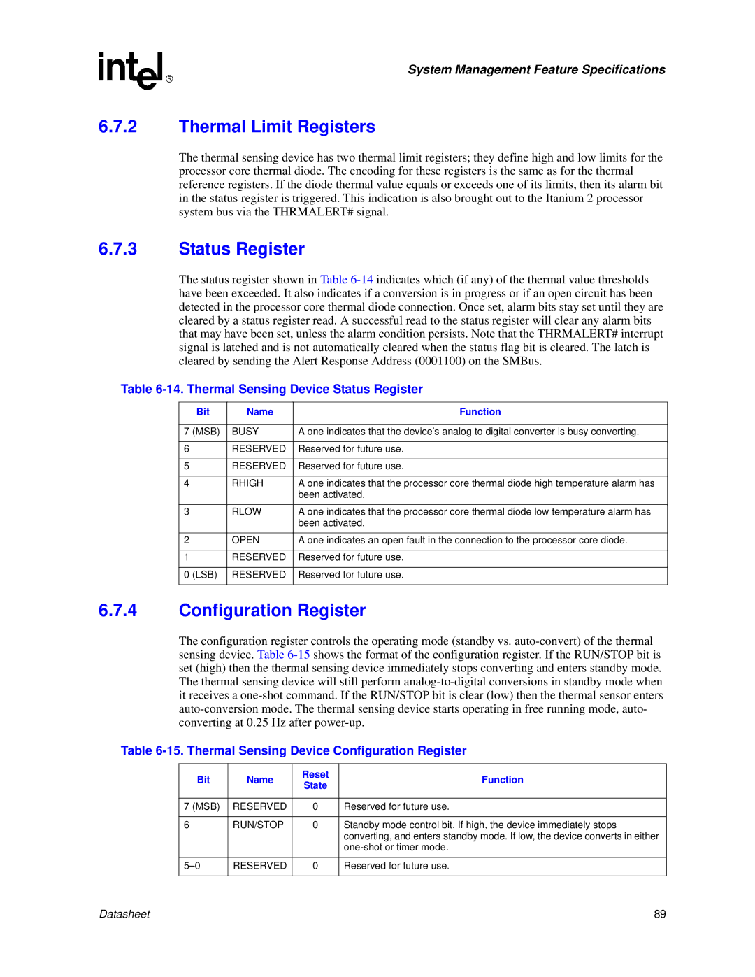
Table 6-14. Thermal Sensing Device Status Register
| Bit | Name | Function |
|
|
|
|
7 | (MSB) | BUSY | A one indicates that the device’s analog to digital converter is busy converting. |
|
|
|
|
6 |
| RESERVED | Reserved for future use. |
|
|
|
|
5 |
| RESERVED | Reserved for future use. |
|
|
|
|
4 |
| RHIGH | A one indicates that the processor core thermal diode high temperature alarm has |
|
|
| been activated. |
|
|
|
|
3 |
| RLOW | A one indicates that the processor core thermal diode low temperature alarm has |
|
|
| been activated. |
|
|
|
|
2 |
| OPEN | A one indicates an open fault in the connection to the processor core diode. |
|
|
|
|
1 |
| RESERVED | Reserved for future use. |
|
|
|
|
0 | (LSB) | RESERVED | Reserved for future use. |
|
|
|
|
6.7.4Configuration Register
The configuration register controls the operating mode (standby vs.
Table 6-15. Thermal Sensing Device Configuration Register
Bit | Name | Reset | Function | |
State | ||||
|
|
| ||
|
|
|
| |
7 (MSB) | RESERVED | 0 | Reserved for future use. | |
|
|
|
| |
6 | RUN/STOP | 0 | Standby mode control bit. If high, the device immediately stops | |
|
|
| converting, and enters standby mode. If low, the device converts in either | |
|
|
| ||
|
|
|
| |
RESERVED | 0 | Reserved for future use. | ||
|
|
|
|
Datasheet | 89 |