System Management Feature Specifications
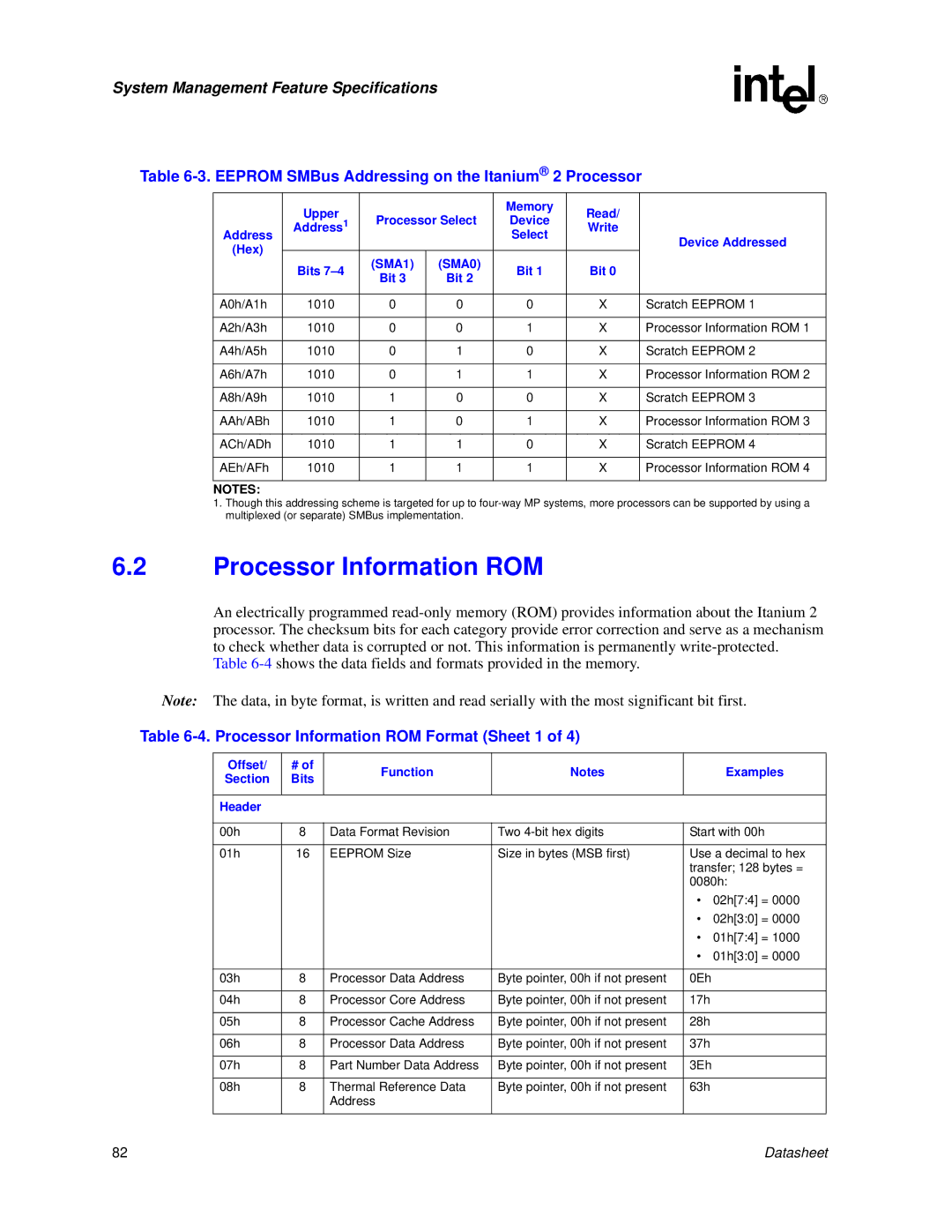
Table 6-3. EEPROM SMBus Addressing on the Itanium® 2 Processor
| Upper |
|
| Memory | Read/ |
|
| Processor Select | Device |
| |||
Address | Address1 | Write |
| |||
|
|
| Select |
| Device Addressed | |
(Hex) |
|
|
|
|
| |
Bits | (SMA1) | (SMA0) | Bit 1 | Bit 0 |
| |
|
| |||||
| Bit 3 | Bit 2 |
| |||
|
|
|
|
| ||
|
|
|
|
|
|
|
A0h/A1h | 1010 | 0 | 0 | 0 | X | Scratch EEPROM 1 |
|
|
|
|
|
|
|
A2h/A3h | 1010 | 0 | 0 | 1 | X | Processor Information ROM 1 |
|
|
|
|
|
|
|
A4h/A5h | 1010 | 0 | 1 | 0 | X | Scratch EEPROM 2 |
|
|
|
|
|
|
|
A6h/A7h | 1010 | 0 | 1 | 1 | X | Processor Information ROM 2 |
|
|
|
|
|
|
|
A8h/A9h | 1010 | 1 | 0 | 0 | X | Scratch EEPROM 3 |
|
|
|
|
|
|
|
AAh/ABh | 1010 | 1 | 0 | 1 | X | Processor Information ROM 3 |
|
|
|
|
|
|
|
ACh/ADh | 1010 | 1 | 1 | 0 | X | Scratch EEPROM 4 |
|
|
|
|
|
|
|
AEh/AFh | 1010 | 1 | 1 | 1 | X | Processor Information ROM 4 |
|
|
|
|
|
|
|
NOTES: |
|
|
|
|
|
|
1.Though this addressing scheme is targeted for up to
6.2Processor Information ROM
An electrically programmed
Table
Note: The data, in byte format, is written and read serially with the most significant bit first.
Table 6-4. Processor Information ROM Format (Sheet 1 of 4)
Offset/ | # of | Function | Notes |
| Examples |
Section | Bits |
| |||
|
|
|
| ||
|
|
|
|
|
|
Header |
|
|
|
|
|
|
|
|
|
| |
00h | 8 | Data Format Revision | Two | Start with 00h | |
|
|
|
|
| |
01h | 16 | EEPROM Size | Size in bytes (MSB first) | Use a decimal to hex | |
|
|
|
| transfer; 128 bytes = | |
|
|
|
| 0080h: | |
|
|
|
| • | 02h[7:4] = 0000 |
|
|
|
| • | 02h[3:0] = 0000 |
|
|
|
| • | 01h[7:4] = 1000 |
|
|
|
| • | 01h[3:0] = 0000 |
|
|
|
|
|
|
03h | 8 | Processor Data Address | Byte pointer, 00h if not present | 0Eh |
|
|
|
|
|
|
|
04h | 8 | Processor Core Address | Byte pointer, 00h if not present | 17h |
|
|
|
|
|
|
|
05h | 8 | Processor Cache Address | Byte pointer, 00h if not present | 28h |
|
|
|
|
|
|
|
06h | 8 | Processor Data Address | Byte pointer, 00h if not present | 37h |
|
|
|
|
|
|
|
07h | 8 | Part Number Data Address | Byte pointer, 00h if not present | 3Eh |
|
|
|
|
|
|
|
08h | 8 | Thermal Reference Data | Byte pointer, 00h if not present | 63h |
|
|
| Address |
|
|
|
|
|
|
|
|
|
82 | Datasheet |