Electrical Specifications
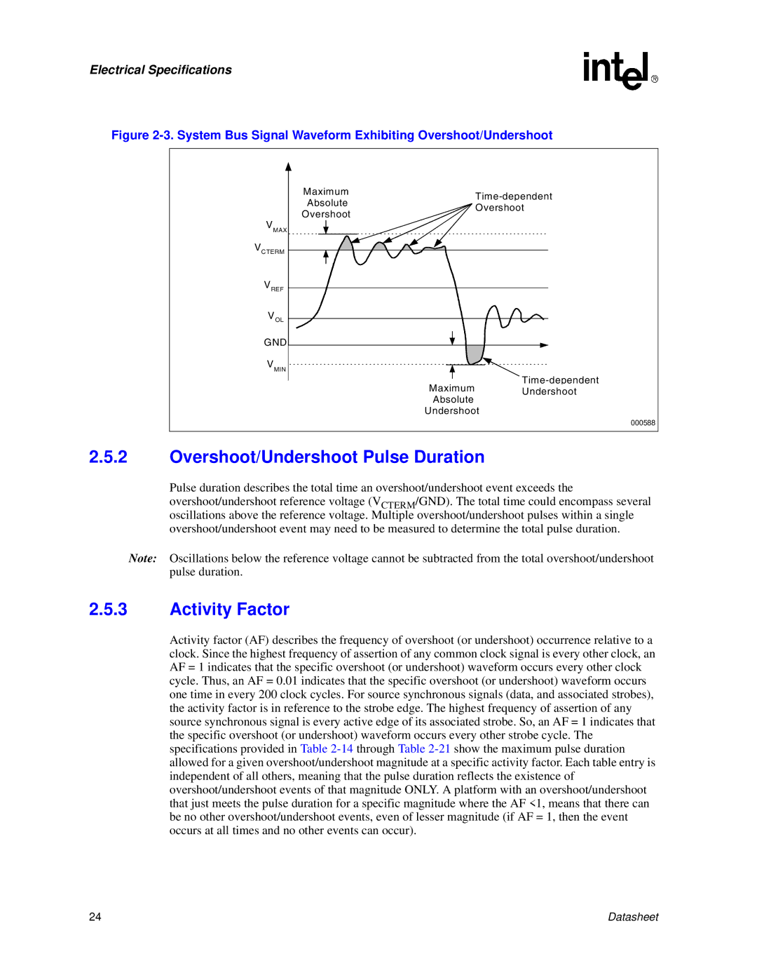
Figure 2-3. System Bus Signal Waveform Exhibiting Overshoot/Undershoot
Maximum | ||
Absolute | ||
Overshoot | ||
Overshoot | ||
|
VMAX
VCTERM
VREF
VOL
GND
VMIN
Maximum Undershoot
Absolute
Undershoot
000588
2.5.2Overshoot/Undershoot Pulse Duration
Pulse duration describes the total time an overshoot/undershoot event exceeds the overshoot/undershoot reference voltage (VCTERM/GND). The total time could encompass several oscillations above the reference voltage. Multiple overshoot/undershoot pulses within a single overshoot/undershoot event may need to be measured to determine the total pulse duration.
Note: Oscillations below the reference voltage cannot be subtracted from the total overshoot/undershoot pulse duration.
2.5.3Activity Factor
Activity factor (AF) describes the frequency of overshoot (or undershoot) occurrence relative to a clock. Since the highest frequency of assertion of any common clock signal is every other clock, an AF = 1 indicates that the specific overshoot (or undershoot) waveform occurs every other clock cycle. Thus, an AF = 0.01 indicates that the specific overshoot (or undershoot) waveform occurs one time in every 200 clock cycles. For source synchronous signals (data, and associated strobes), the activity factor is in reference to the strobe edge. The highest frequency of assertion of any source synchronous signal is every active edge of its associated strobe. So, an AF = 1 indicates that the specific overshoot (or undershoot) waveform occurs every other strobe cycle. The specifications provided in Table
24 | Datasheet |
