5Thermal Specifications
This chapter provides a description of the thermal features relating to the Itanium 2 processor.
5.1Thermal Features
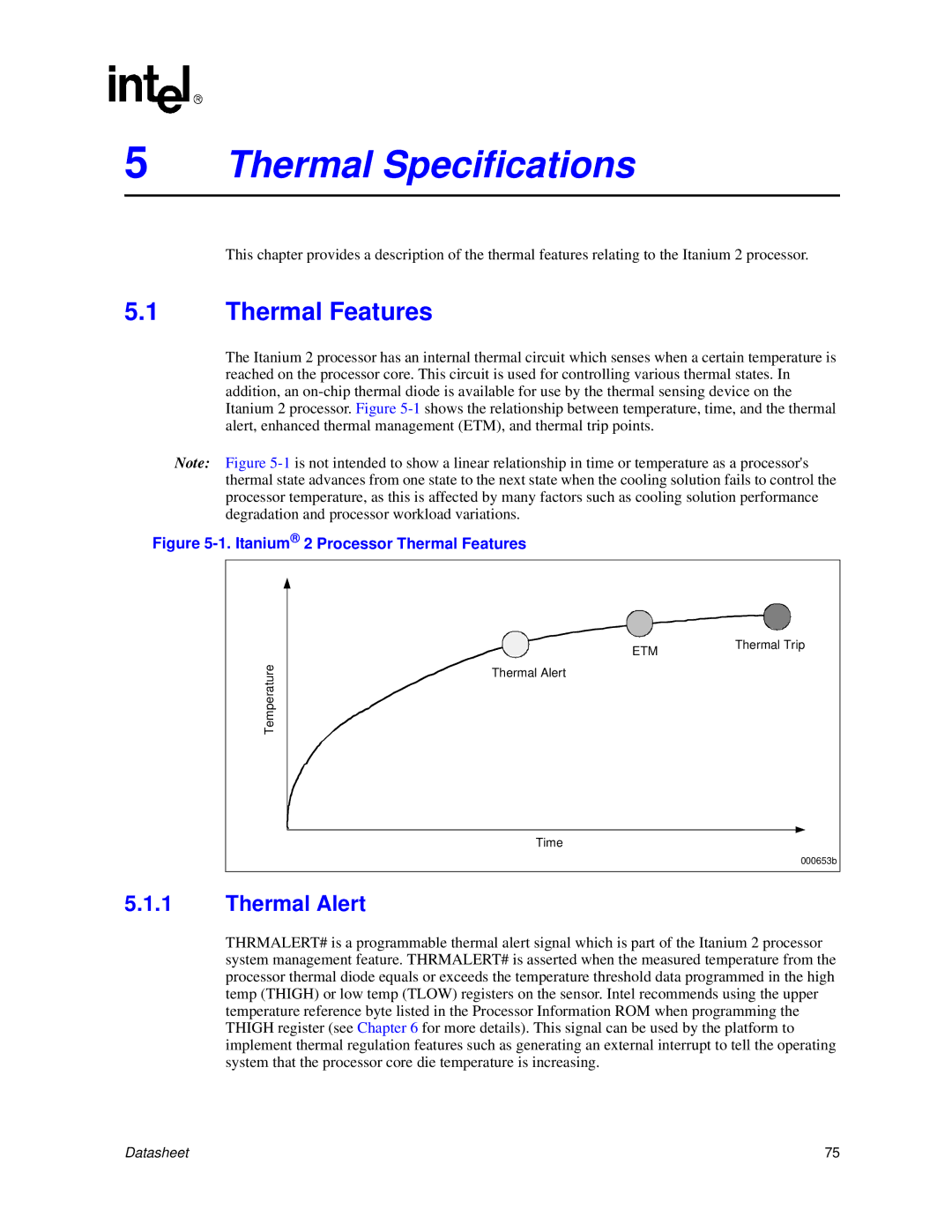
The Itanium 2 processor has an internal thermal circuit which senses when a certain temperature is reached on the processor core. This circuit is used for controlling various thermal states. In addition, an
Note: Figure
Figure 5-1. Itanium® 2 Processor Thermal Features
Temperature
5.1.1Thermal Alert
ETM | Thermal Trip |
|
Thermal Alert
Time
000653b
THRMALERT# is a programmable thermal alert signal which is part of the Itanium 2 processor system management feature. THRMALERT# is asserted when the measured temperature from the processor thermal diode equals or exceeds the temperature threshold data programmed in the high temp (THIGH) or low temp (TLOW) registers on the sensor. Intel recommends using the upper temperature reference byte listed in the Processor Information ROM when programming the THIGH register (see Chapter 6 for more details). This signal can be used by the platform to implement thermal regulation features such as generating an external interrupt to tell the operating system that the processor core die temperature is increasing.
Datasheet | 75 |