Electrical Specifications
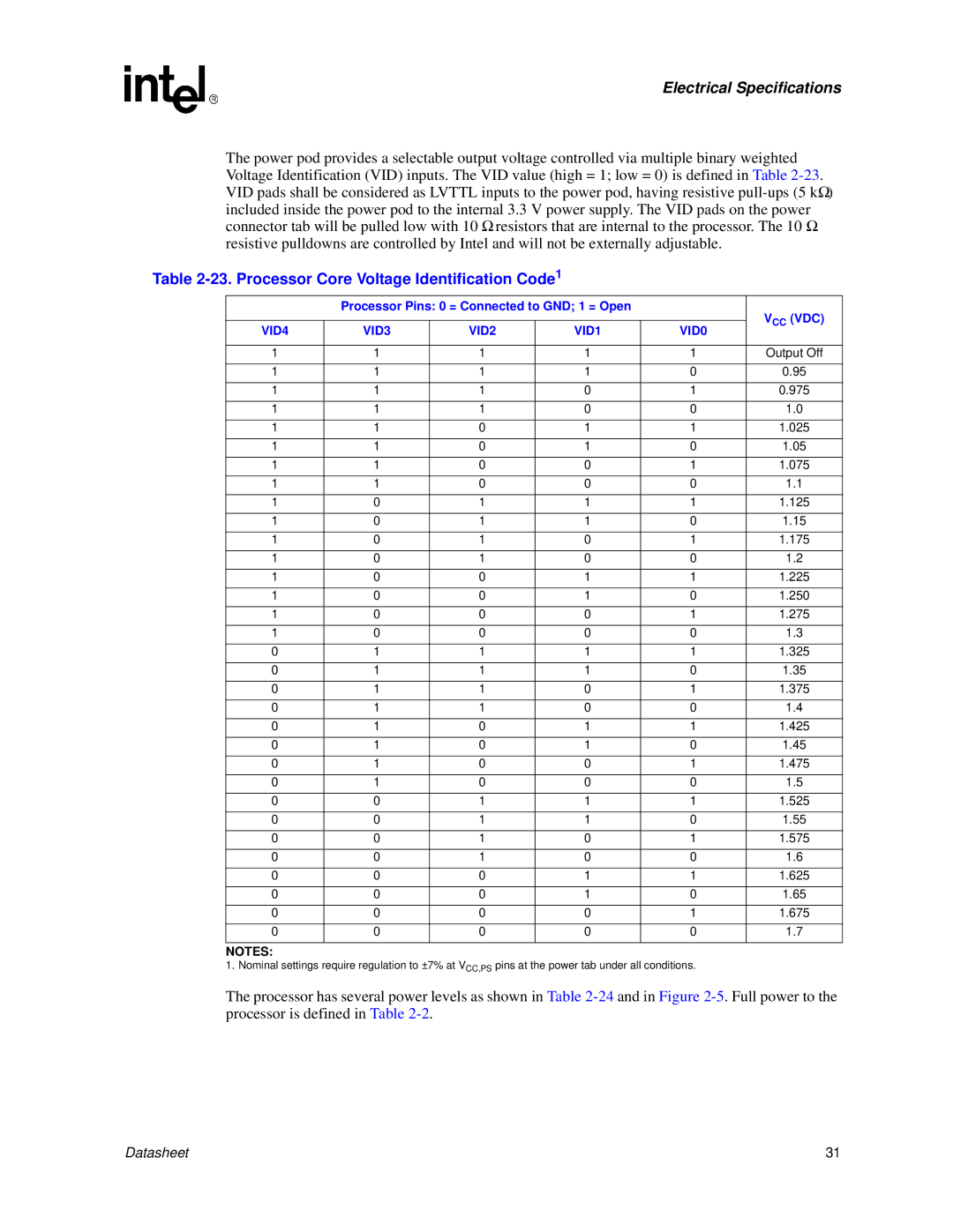
The power pod provides a selectable output voltage controlled via multiple binary weighted Voltage Identification (VID) inputs. The VID value (high = 1; low = 0) is defined in Table
Table 2-23. Processor Core Voltage Identification Code1
| Processor Pins: 0 = Connected to GND; 1 = Open |
| VCC (VDC) | |||
|
|
|
|
| ||
VID4 | VID3 | VID2 | VID1 | VID0 | ||
| ||||||
|
|
|
|
|
| |
1 | 1 | 1 | 1 | 1 | Output Off | |
1 | 1 | 1 | 1 | 0 | 0.95 | |
1 | 1 | 1 | 0 | 1 | 0.975 | |
1 | 1 | 1 | 0 | 0 | 1.0 | |
1 | 1 | 0 | 1 | 1 | 1.025 | |
1 | 1 | 0 | 1 | 0 | 1.05 | |
1 | 1 | 0 | 0 | 1 | 1.075 | |
1 | 1 | 0 | 0 | 0 | 1.1 | |
1 | 0 | 1 | 1 | 1 | 1.125 | |
1 | 0 | 1 | 1 | 0 | 1.15 | |
1 | 0 | 1 | 0 | 1 | 1.175 | |
1 | 0 | 1 | 0 | 0 | 1.2 | |
1 | 0 | 0 | 1 | 1 | 1.225 | |
1 | 0 | 0 | 1 | 0 | 1.250 | |
1 | 0 | 0 | 0 | 1 | 1.275 | |
1 | 0 | 0 | 0 | 0 | 1.3 | |
0 | 1 | 1 | 1 | 1 | 1.325 | |
0 | 1 | 1 | 1 | 0 | 1.35 | |
0 | 1 | 1 | 0 | 1 | 1.375 | |
0 | 1 | 1 | 0 | 0 | 1.4 | |
0 | 1 | 0 | 1 | 1 | 1.425 | |
0 | 1 | 0 | 1 | 0 | 1.45 | |
0 | 1 | 0 | 0 | 1 | 1.475 | |
0 | 1 | 0 | 0 | 0 | 1.5 | |
0 | 0 | 1 | 1 | 1 | 1.525 | |
0 | 0 | 1 | 1 | 0 | 1.55 | |
0 | 0 | 1 | 0 | 1 | 1.575 | |
0 | 0 | 1 | 0 | 0 | 1.6 | |
0 | 0 | 0 | 1 | 1 | 1.625 | |
0 | 0 | 0 | 1 | 0 | 1.65 | |
0 | 0 | 0 | 0 | 1 | 1.675 | |
0 | 0 | 0 | 0 | 0 | 1.7 | |
NOTES:
1. Nominal settings require regulation to ±7% at VCC,PS pins at the power tab under all conditions.
The processor has several power levels as shown in Table
Datasheet | 31 |
