Electrical Specifications
Table
Absolute |
|
|
| Pulse Duration (ns) |
|
|
| |||
Maximum (V) |
|
|
|
|
|
| ||||
|
|
|
|
|
|
|
|
| ||
|
|
|
|
|
|
|
|
|
|
|
1.6 | 2.4567 | 3 | 3 |
| 3 |
| 3 | 3 | 3 | |
|
|
|
|
|
|
|
|
|
|
|
1.55 | 3 | 3 | 3 |
| 3 |
| 3 | 3 | 3 | |
|
|
|
|
|
|
|
|
|
|
|
1.5 | 3 | 3 | 3 |
| 3 |
| 3 | 3 | 3 | |
|
|
|
|
|
|
|
|
|
|
|
NOTES:
1. Activity Factor = 1 means signal toggles every 6 ns.
2.6Power Pod Connector Signals
Power delivery for the Itanium 2 processor is from a
Table
Table 2-22. Itanium® 2 Processor Power Pod Connector Signals
Group Name | Signals |
|
|
Power Pod Connector | OUTEN, CPUPRES#, PPODGD#, VCC, VCCMON, GND, VSSMON, VID[4:0] |
|
|
Warning: If the power supply cannot supply the voltages requested by the components in the Itanium 2 processor, then it must disable itself.
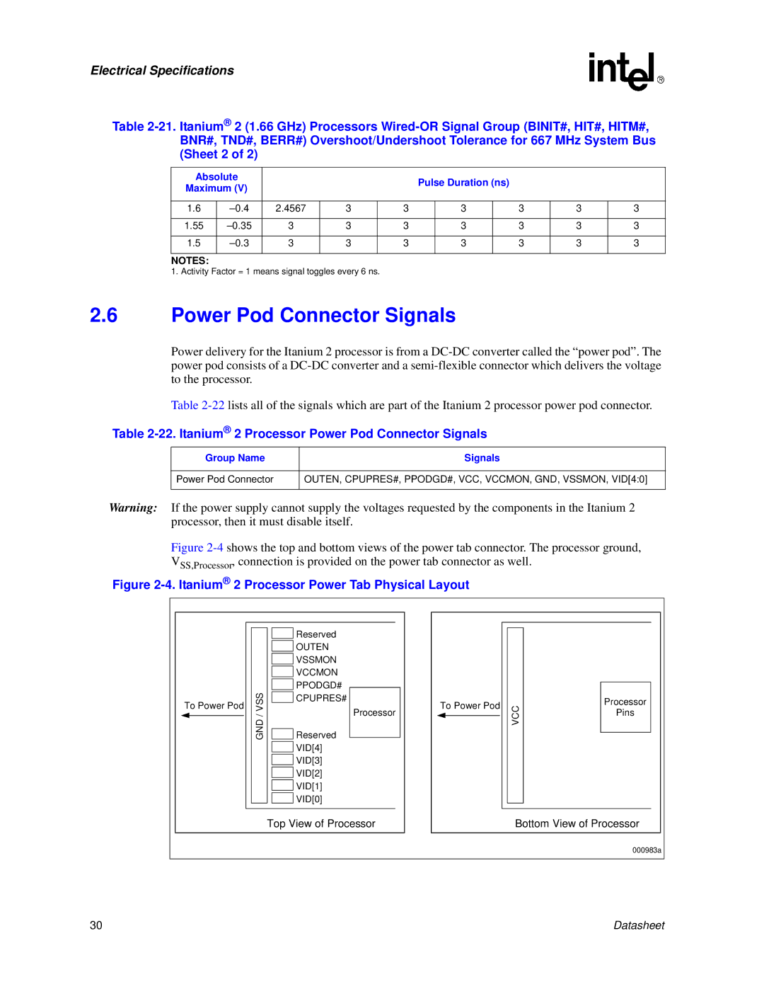
Figure 2-4 shows the top and bottom views of the power tab connector. The processor ground, VSS,Processor, connection is provided on the power tab connector as well.
Figure 2-4. Itanium® 2 Processor Power Tab Physical Layout
|
|
| Reserved |
|
|
|
|
|
|
|
| OUTEN |
|
|
|
|
|
|
|
|
|
|
|
|
| |
|
|
| VSSMON |
|
|
|
|
|
|
|
|
|
|
|
|
| |
|
|
| VCCMON |
|
|
|
|
|
|
|
|
|
|
|
|
| |
| VSS/GND |
| PPODGD# |
|
|
|
| VCC |
|
|
|
|
|
| |||
|
|
|
|
|
| |||
|
| Reserved |
|
|
|
| ||
To Power Pod |
| CPUPRES# |
|
| To Power Pod |
| ||
|
| Processor |
|
| ||||
|
|
|
|
|
|
|
| |
|
|
|
|
|
|
|
|
|
|
|
|
|
|
|
|
|
|
|
|
|
|
|
|
|
|
|
![]() VID[4]
VID[4]
![]() VID[3]
VID[3]
![]() VID[2]
VID[2]
![]() VID[1]
VID[1]
![]() VID[0]
VID[0]
Processor
Pins
Top View of Processor | Bottom View of Processor |
000983a
30 | Datasheet |