Electrical Specifications
NOTES:
1.This is the tolerance requirement, across a 200 MHz bandwidth, at the processor pins. The requirement at the processor pins accounts for voltage drops (and impedance discontinuities) at the processor pins and to the processor core. In addition to the ±1.5% DC tolerance, there is a ±3.5% AC tolerance for a total of ±5% tolerance.
2.The Itanium® 2 processor system bus is terminated at each end of the system bus. The Itanium 2 processor supports both on- die and
3.Maximum termination voltage current on one terminating agent.
4.For all core frequencies and cache sizes.
5.Maximum thermal design envelope is provided for the design of thermal/chassis solutions.
6.Maximum thermal design power is an estimate of the power dissipation for the Itanium 2 processor offering while executing a
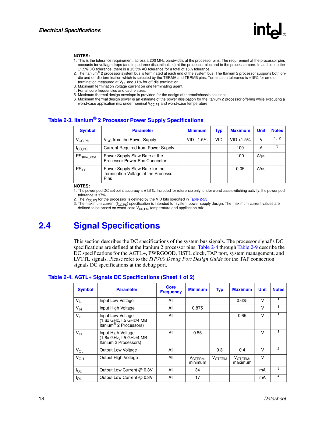
Table 2-3. Itanium® 2 Processor Power Supply Specifications
Symbol | Parameter | Minimum | Typ | Maximum | Unit | Notes | |
|
|
|
|
|
|
|
|
VCC,PS | VCC from the Power Supply | VID | VID | VID +1.5% | V | 1, | 2 |
|
| ||||||
ICC,PS | Current Required from Power Supply |
|
| 100 | A | 3 |
|
|
|
|
| ||||
PSslew_rate | Power Supply Slew Rate at the |
|
| 100 | A/µs |
|
|
| Processor Power Pod Connector |
|
|
|
|
|
|
|
|
|
|
|
|
|
|
PSTT | Power Supply Slew Rate for the |
|
| 0.05 | A/ns |
|
|
| Termination Voltage at the Processor |
|
|
|
|
|
|
| Pins |
|
|
|
|
|
|
|
|
|
|
|
|
|
|
NOTES: |
|
|
|
|
|
|
|
1.The power pod DC set point accuracy is ±1.5%. Included for reference only, under worst case switching activity, the power pod tolerance is ±7%.
2.The VCC,PS for the processor is defined by the VID bits specified in Table
3.The maximum current (ICC,PS) specification is intended for system power supply design. The maximum current values are defined to be based on
2.4Signal Specifications
This section describes the DC specifications of the system bus signals. The processor signal’s DC specifications are defined at the Itanium 2 processor pins. Table
Table 2-4. AGTL+ Signals DC Specifications (Sheet 1 of 2)
Symbol | Parameter | Core | Minimum | Typ | Maximum | Unit | Notes | |
Frequency | ||||||||
|
|
|
|
|
|
| ||
|
|
|
|
|
|
|
| |
VIL | Input Low Voltage | All |
|
| 0.625 | V | 1 | |
|
|
| ||||||
VIH | Input High Voltage | All | 0.875 |
|
| V | 1 | |
|
|
| ||||||
VIL | Input Low Voltage | All |
|
| 0.65 | V | 1 | |
|
|
| ||||||
| (1.6x GHz, I.5 GHz/4 MB |
|
|
|
|
|
| |
| Itanium® 2 Processors) |
|
|
|
|
|
| |
VIH | Input High Voltage | All | 0.85 |
|
| V | 1 | |
|
|
| ||||||
| (1.6x GHz, I.5 GHz/4 MB |
|
|
|
|
|
| |
| Itanium 2 Processors) |
|
|
|
|
|
| |
|
|
|
|
|
|
|
| |
VOL | Output Low Voltage | All |
| 0.3 | 0.4 | V | 2 | |
|
| |||||||
VOH | Output High Voltage | All | VCTERM, | VCTERM | VCTERM, | V |
| |
|
|
| minimum |
| maximum |
|
| |
|
|
|
|
|
|
|
| |
IOL | Output Low Current @ 0.3V | All | 34 |
|
| mA | 3 | |
|
|
| ||||||
IOL | Output Low Current @ 0.3V | All | 17 |
|
| mA | 4 | |
|
|
|
18 | Datasheet |