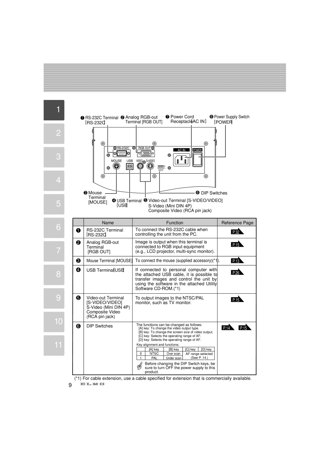
Connector Panel
1
|
|
| Analog | Power Cord | Power Supply Switch | |||||
|
|
|
| Terminal [RGB OUT] | Receptacle[AC IN] | [POWER] | ||||
2 |
|
|
|
|
|
|
|
|
|
|
3 |
|
|
|
|
|
|
|
|
|
|
|
|
|
|
|
| 0 |
|
|
|
|
|
|
|
|
|
| 1 |
|
|
|
|
|
|
|
|
|
| A BCD |
|
|
|
|
4 |
|
|
|
|
|
|
|
|
|
|
|
| Mouse |
|
|
|
|
| DIP Switches |
| |
5 |
| Terminal | USB Terminal |
| ||||||
| [MOUSE] |
| ||||||||
| [USB] |
|
|
| ||||||
|
|
|
|
| ||||||
|
|
|
|
|
| Composite Video (RCA pin jack) |
|
| ||
6 |
| Name |
|
|
|
| Function |
| Reference Page | |
1 |
| To connect the |
| P.32 | ||||||
|
|
|
| controlling the unit from the PC. |
| |||||
|
|
|
|
|
| |||||
| 2 | Analog |
| Image is output when this terminal is |
| P.15 | ||||
7 |
| Terminal |
|
| connected to RGB input equipment |
| ||||
|
|
|
|
| ||||||
| [RGB OUT] |
|
| (e.g., LCD projector, |
|
| ||||
| 3 | Mouse Terminal [MOUSE] | To connect the mouse (supplied accessory)(*1). | P.13 | ||||||
8 | 4 | USB Terminal [USB] |
| If connected to | personal | computer with | P.26 | |||
|
|
|
| the attached USB cable, it is possible to | ||||||
|
|
|
|
| ||||||
|
|
|
|
| transfer images and control the unit by |
| ||||
|
|
|
|
| using the software in the attached Utility |
| ||||
|
|
|
|
| Software |
|
|
| ||
9 | 5 |
| To output images to the NTSC/PAL |
| P.15 | |||||
|
|
|
| monitor, such as TV monitor. |
|
| ||||
|
|
|
|
|
|
|
| |||
|
| Composite Video |
|
|
|
|
|
|
| |
10 |
| (RCA pin jack) |
|
|
|
|
|
|
|
|
6 | DIP Switches |
|
| The functions can be changed as follows: | P.14 | P.15 | ||||
|
|
| ||||||||
|
|
|
|
| ◊[A] key: To change the video output type. | |||||
|
|
|
|
| ◊[B] key: To change the screen size of video output. |
|
| |||
|
|
|
|
| ◊[C] key: Selects the operating range of AF. |
|
| |||
11 |
|
|
|
| ◊[D] key: Selects the operating range of AF. |
|
| |||
|
|
|
| Key alignment and functions: |
|
|
| |||
|
|
|
|
|
|
|
| |||
|
|
|
|
|
| [A] key | [B] key | [C] key [D] key |
|
|
|
|
|
|
| 0 | NTSC | Over scan | AF range selected |
|
|
|
|
|
|
| 1 | PAL | Under scan | (See P. 14.) |
|
|
|
|
|
|
|
| Before changing the DIP Switch keys, be |
|
| ||
|
|
|
|
|
| sure to turn OFF the power supply to this |
|
| ||
|
|
|
|
|
| product. |
|
|
|
|
(*1) For cable extension, use a cable specified for extension that is commercially available.
9
