2400S specifications
The Emerson 2400S is a versatile and sophisticated process automation controller designed for industries that require precision and reliability. This advanced controller is recognized for its high performance in monitoring and controlling complex processes in various applications, including oil and gas, chemical processing, and water treatment.One of the standout features of the Emerson 2400S is its exceptional processing power. With a robust architecture, it can handle multiple tasks simultaneously, allowing for real-time data processing and quick system responses. This capability is essential in dynamic environments where conditions change rapidly, ensuring that operations remain stable and efficient.
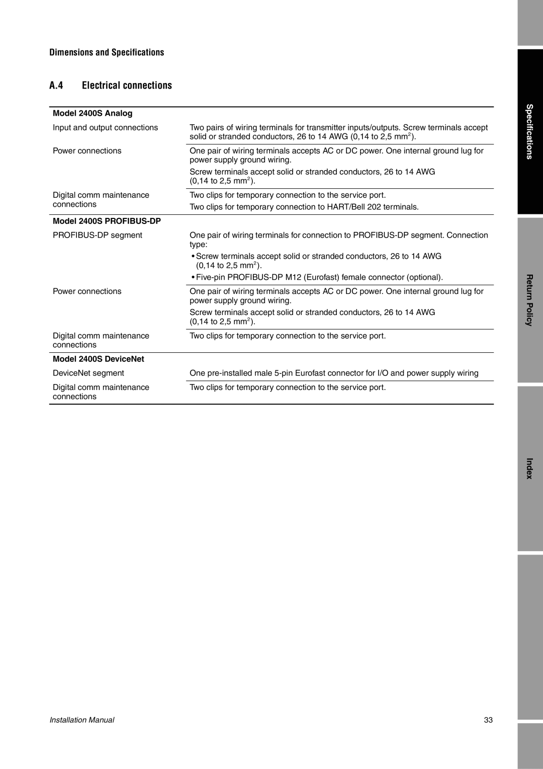
The 2400S also boasts an extensive range of input/output options. It supports various types of signals, including analog, digital, and serial communications. This flexibility allows integration with a wide range of sensors and devices, ensuring comprehensive monitoring and control capabilities across different systems.
One of the key technologies integrated into the Emerson 2400S is the use of advanced algorithms for predictive maintenance and process optimization. By analyzing historical data and current conditions, the controller can forecast potential issues and suggest corrective actions. This proactive approach not only enhances system reliability but also minimizes downtime and operational costs.
In addition to its powerful processing and predictive capabilities, the 2400S features a user-friendly interface. The graphical display allows operators to visualize critical data easily, making it simpler to manage operations and respond to alerts. This feature is crucial in enhancing overall situational awareness within control rooms.
The Emerson 2400S is also designed with high safety standards in mind. It includes built-in redundancies and fault-tolerance features, ensuring that operations can continue even in the event of component failures. This level of reliability is particularly important in industries where safety is paramount.
Moreover, the controller is equipped with advanced cybersecurity measures to protect against potential threats. With the increasing reliance on connected devices and networks, ensuring the integrity of the control system is critical. The Emerson 2400S employs robust encryption and secure access protocols to safeguard sensitive data.
In conclusion, the Emerson 2400S is a state-of-the-art process automation controller that combines high performance, versatility, and advanced safety features. Its ability to support various input/output configurations, coupled with predictive maintenance technologies and a user-friendly interface, makes it an ideal choice for industries requiring reliable and efficient process control.