Backplane Connections and Installation Rules
These DFE modules have connections to both FTM1 and FTM2 backplanes, enabling them to route frames between the two backplanes and all modules in the 6C107 chassis. However, the older first (6x1xx), second (6x2xx), and third (6x3xx) generation modules are still managed using their own Local Management and are not subject to management by the DFE module management entity.
The Matrix N1 (7C111), Matrix N3 (7C103) and Matrix N7 (7C107) chassis have only FTM2 connections and support only DFE modules. The Matrix N5 (7C105‐P) has FTM2 connections and also supports PoE‐compliant DFE modules.
Module Placement and Installation Rules
The DFE‐Platinum modules can be installed in a Matrix E7 (refer to “Matrix E7 Chassis Module Placement,” below, for placement rules), Matrix N1, Matrix N3, Matrix N5, or Matrix N7 chassis. The Matrix N1, Matrix N3, Matrix N5, and Matrix N7 chassis support only DFE Series modules and there are no particular rules for installing modules.
Matrix E7 Chassis Module Placement
Depending on the modules being installed in the Matrix E7 chassis and to help ensure proper operation, consider the following examples and rules for module placement in the chassis. Figure 3‐1 shows six examples of chassis module placement. These examples are described below along with the applicable module placement rule.
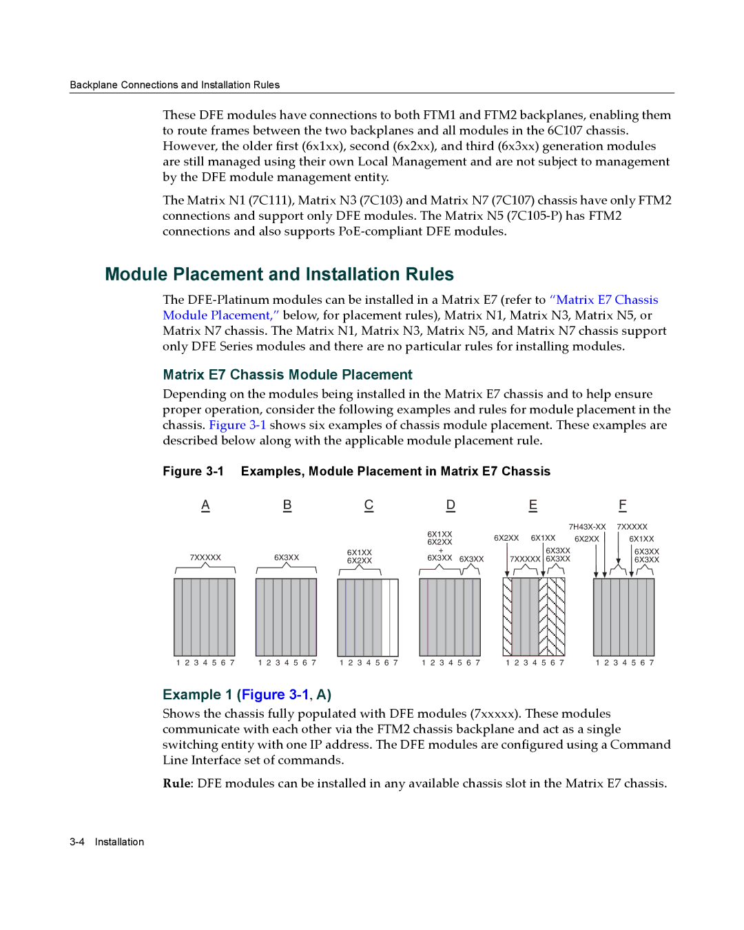
Figure 3-1 Examples, Module Placement in Matrix E7 Chassis
|
|
| A |
|
|
| B |
|
|
| C |
|
|
| D |
|
|
| E |
|
| F | |||||||||||||||||||||||
|
|
|
|
|
|
|
|
|
|
|
|
|
|
|
|
|
|
|
|
|
|
|
| 6X1XX |
|
|
|
|
|
|
|
| 7XXXXX | ||||||||||||
|
|
|
|
|
|
|
|
|
|
|
|
|
|
|
|
|
|
|
|
|
|
|
| 6X2XX 6X1XX | 6X2XX |
| 6X1XX | ||||||||||||||||||
|
|
|
|
|
|
|
|
|
|
|
|
|
|
|
|
|
|
|
|
|
|
|
| 6X2XX |
| ||||||||||||||||||||
| 7XXXXX |
|
| 6X3XX |
| 6X1XX | + |
|
|
|
|
|
|
|
|
|
| 6X3XX |
|
|
| 6X3XX | |||||||||||||||||||||||
|
|
|
| 6X2XX | 6X3XX 6X3XX |
| 7XXXXX 6X3XX |
|
|
| 6X3XX | ||||||||||||||||||||||||||||||||||
|
|
|
|
|
|
|
|
|
|
|
|
|
|
|
|
|
|
|
|
|
|
|
|
|
|
|
|
|
|
|
|
|
|
|
|
|
|
|
|
|
|
|
|
|
|
|
|
|
|
|
|
|
|
|
|
|
|
|
|
|
|
|
|
|
|
|
|
|
|
|
|
|
|
|
|
|
|
|
|
|
|
|
|
|
|
|
|
|
|
|
|
1 2 3 4 5 6 7 | 1 2 3 4 5 6 7 | 1 2 3 4 5 6 7 | 1 2 3 4 5 6 7 | 1 2 3 4 5 6 7 | 1 2 3 4 5 6 7 |
Example 1 (Figure 3-1, A)
Shows the chassis fully populated with DFE modules (7xxxxx). These modules communicate with each other via the FTM2 chassis backplane and act as a single switching entity with one IP address. The DFE modules are configured using a Command Line Interface set of commands.
Rule: DFE modules can be installed in any available chassis slot in the Matrix E7 chassis.