Enterasys Matrix
Page
Page
Class a ITE Notice Clase A. Aviso de ITE
Product Safety
Federal Communications Commission FCC Notice
Industry Canada Notice
Electromagnetic Compatibility EMC
Compatibilidad Electromágnetica EMC
Elektro- magnetische Kompatibilität EMC
Supplement to Product Instructions
Safety Information Class 1 Laser Transceivers
Vcci Notice
Bsmi EMC Statement Taiwan
USA
Declaration of Conformity
Enterasys NETWORKS, INC. Firmware License Agreement
Viii
Page
Page
Contents
Appendix C About PoE Power over Ethernet
Troubleshooting
Appendix a Specifications
Appendix B Mode Switch Settings and Option Installations
Tables
Figures
Xiv
About This Guide
Who Should Use This Guide
Important Notice
How to Use This Guide
Related Documents
For Refer to
Following conventions are used in this guide
Conventions Used in This Guide
Support@enterasys.com
Getting Help
For information about Refer to
Introduction
Overview of DFE-Platinum Series Module Capabilities
DFE-Platinum 7H4385-49 PoE Module
7H4385-49 DFE-Platinum Module
Management
Switch Configuration Using WebView
Switch Configuration Using CLI Commands
Connectivity
Secure Networks Policy Support
Lanview Diagnostic LEDs
Link Aggregation
Network Requirements
Module Placement in a Matrix E7 Chassis
FTM Bridge Function and Optional Interface Module
10BASE-T Network
100BASE-TX Network
100BASE-TX Network Network Requirements
Installation
Installation Site Requirement
Contents of 7H4385-49 Module Carton Quantity
Unpacking the DFE Module
Installing Optional Network Expansion Module NEM
Backplane Connections and Installation Rules
FTM1 and FTM2 Connectivity
Module Placement and Installation Rules
Matrix E7 Chassis Module Placement
Example 1 -1,A
Example 2 -1,B
Example 3 -1, C
Example 4 -1,D
Example 6 -1, F
Example 5 -1, E
DFE-Platinum Series Hardware Installation Guide
To install the 7H4385‐49, refer to ‐2 and proceed as follows
DFE-Platinum Series Hardware Installation Guide
No bottom connectors in Matrix N7chassis
Installing the 7H4385-49 into Matrix N1, N3, or N5 Chassis
Installation
Installing Module into Matrix N3, N5, or N1 Chassis N3 shown
Connecting 48 Vdc Power for PoE Operation
Connecting UTP Cables to 7H4385-49
Connecting to the Network
Making the UTP Connections
Connecting a Twisted Pair Segment with RJ45 Connector
RX+ TX+
TX1+ RX1 TX2+ TX3+ RX3 RX2 TX4+ RX4
Verifying PoE Port Status
Connecting to COM Port for Local Management
What Is Needed
Connecting to an IBM PC or Compatible Device
Parameter Setting
Connecting to a VT Series Terminal
10 Connecting a VT Series Terminal
Connecting to a Modem
11 Connecting to a Modem
COM Port Adapter Wiring and Signal Diagram RJ45
Adapter Wiring and Signal Assignments
RJ45 DB25
Modem Port Adapter Wiring and Signal Diagram
Completing the Installation
Completing the Installation of a New System
First-Time Log-In Using a Console Port Connection
12 Matrix DFE Startup Screen Example N7 Chassis
Enter
Logging in with an Administratively-Configured User Account
Troubleshooting
Using Lanview
About the Management Mgmt LED
Viewing the PoE Port Status
Viewing the Receive and Transmit Activity
Color State Recommended Action
LED
Amber and Alternating 67% on, 33%
RX/TX Indications in Standard Mode
RX/TX
DFE-Platinum Series Configuration Guide
Troubleshooting Checklist
Problem Possible Cause Recommended Action
Troubleshooting Checklist
Overview of DFE Module Shutdown Procedure
OFFLINE/RESET Switch
Recommended Shutdown Procedure Using OFFLINE/RESET Switch
Last Resort Shutdown Procedure Using OFFLINE/RESET Switch
Processors/Memory
Specifications
DFE Module Specifications
Table A-1 7H4385-49 Specifications
Environmental
Table A-1 7H4385-49 Specifications Physical
Table A-2 COM Port Pin Assignments Signal Name Input/Output
COM Port Pinout Assignments
Table A-3 Compliance Standards Regulatory Compliance
Regulatory Compliance
Regulatory Compliance Specifications
Required Tools
Mode Switch Settings and Option Installations
Setting the Mode Switches
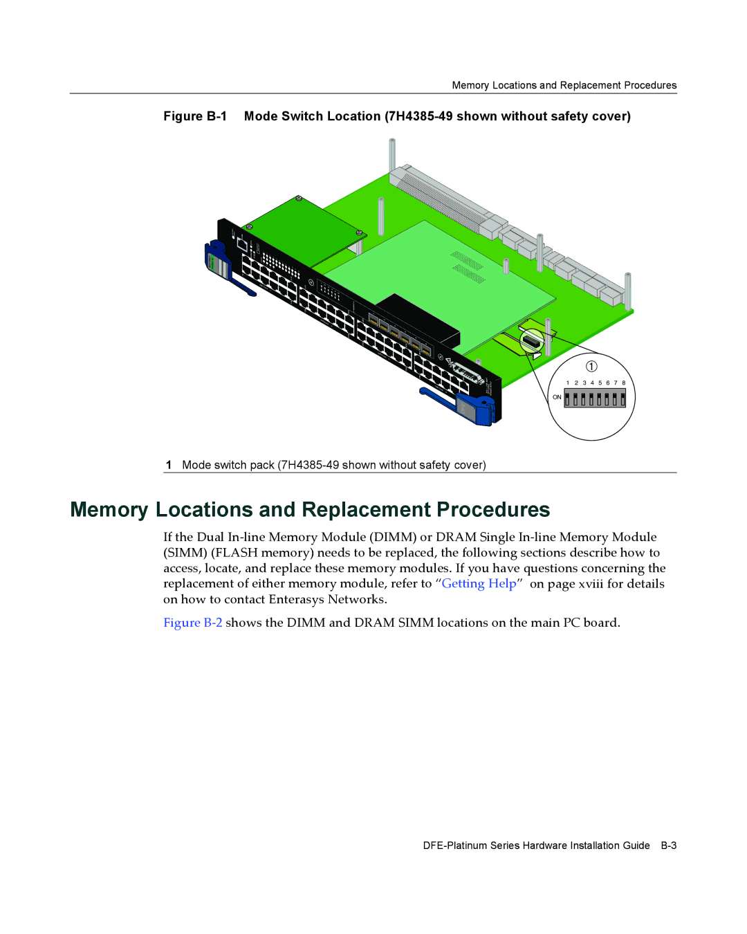
Memory Locations and Replacement Procedures
Memory Locations and Replacement Procedures
Gaining Access to Memory Modules
Gaining Access to Memory Modules
Removing the Safety Cover
Figure B-3 Removing the Safety Cover
Removing the Optional Network Expansion Module NEM
Dram Simm Replacement Procedure
Figure B-5 Removing the Existing Dram Simm
Removing the Dram Simm
Figure B-6 Installing the Dram Simm
Installing the Dram Simm
Removing the Dimm
Dimm Replacement Procedure
Installing the Dimm
Installing the Network Expansion Module NEM
Figure B-9 Installing the Network Expansion Module
Reinstalling the Safety Cover
Figure B-10 Installing the Safety Cover
Overview
About PoE Power over Ethernet
Proprietary PD Detection
Table C-2 PoE Status LED Indications PoE Port Status
PoE Port Status LEDs
Overview About PoE Power over Ethernet
Numerics
Index
Pinout assignments console port A-2