Connecting Stacking Cables
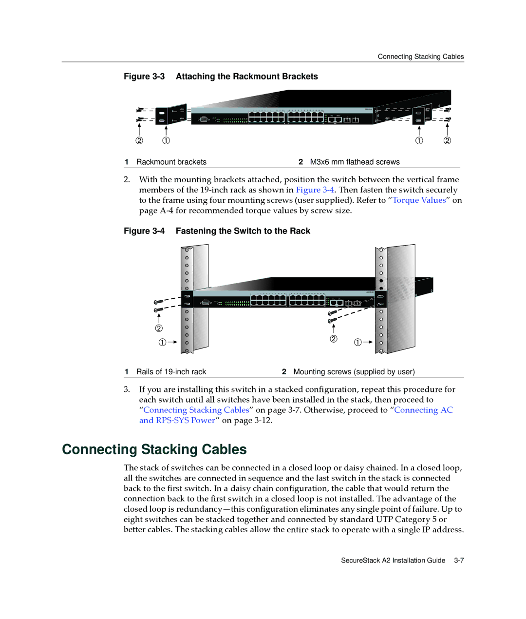
Figure 3-3 Attaching the Rackmount Brackets
1 Rackmount brackets | 2 M3x6 mm flathead screws |
2.With the mounting brackets attached, position the switch between the vertical frame members of the 19‐inch rack as shown in Figure 3‐4. Then fasten the switch securely to the frame using four mounting screws (user supplied). Refer to “Torque Values” on page A‐4 for recommended torque values by screw size.
Figure 3-4 Fastening the Switch to the Rack
1 Rails of | 2 Mounting screws (supplied by user) |
3.If you are installing this switch in a stacked configuration, repeat this procedure for each switch until all switches have been installed in the stack, then proceed to “Connecting Stacking Cables” on page 3‐7. Otherwise, proceed to “Connecting AC and RPS‐SYS Power” on page 3‐12.
Connecting Stacking Cables
The stack of switches can be connected in a closed loop or daisy chained. In a closed loop, all the switches are connected in sequence and the last switch in the stack is connected back to the first switch. In a daisy chain configuration, the cable that would return the connection back to the first switch in a closed loop is not installed. The advantage of the closed loop is
SecureStack A2 Installation Guide