Connecting to the Network
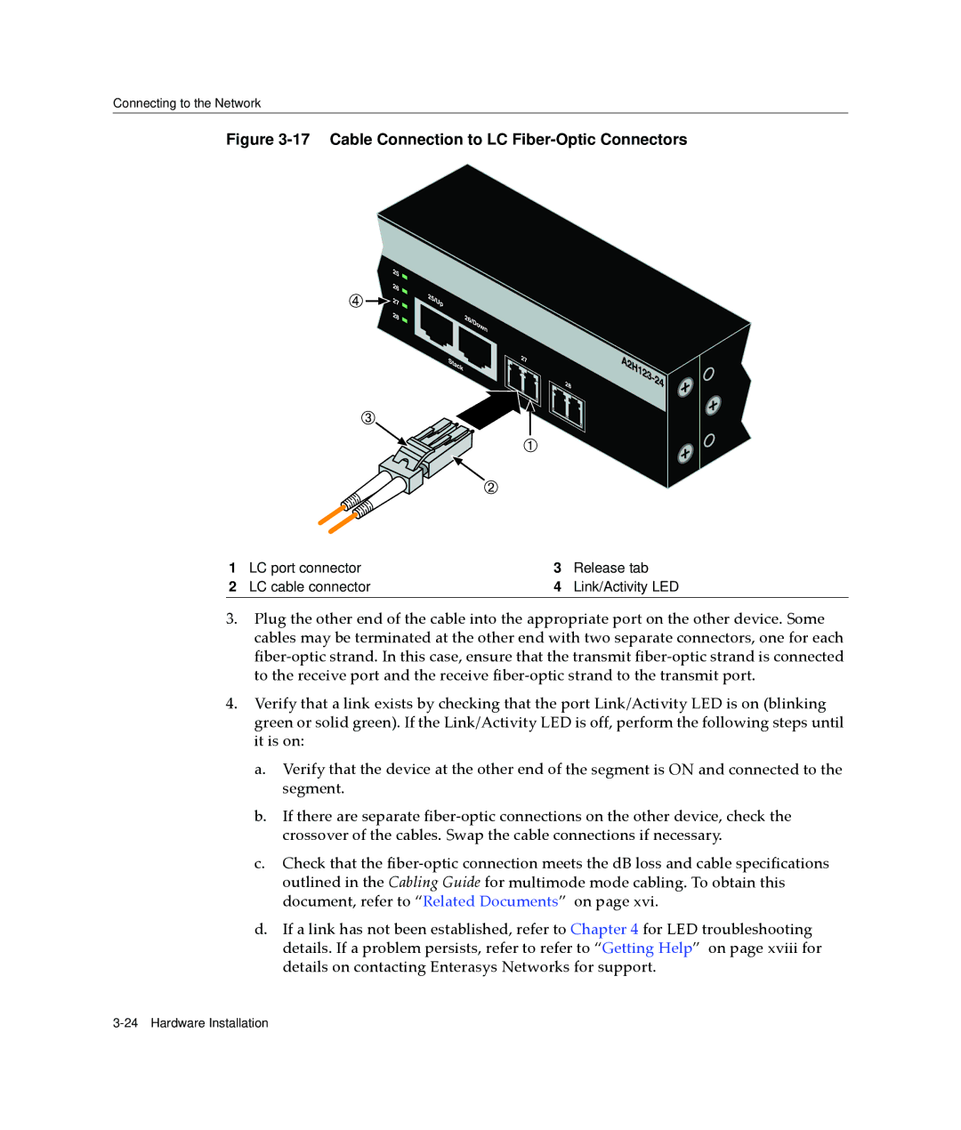
Figure 3-17 Cable Connection to LC Fiber-Optic Connectors
1 | LC port connector | 3 | Release tab |
2 | LC cable connector | 4 | Link/Activity LED |
3.Plug the other end of the cable into the appropriate port on the other device. Some cables may be terminated at the other end with two separate connectors, one for each fiber‐optic strand. In this case, ensure that the transmit fiber‐optic strand is connected to the receive port and the receive fiber‐optic strand to the transmit port.
4.Verify that a link exists by checking that the port Link/Activity LED is on (blinking green or solid green). If the Link/Activity LED is off, perform the following steps until it is on:
a.Verify that the device at the other end of the segment is ON and connected to the segment.
b.If there are separate fiber‐optic connections on the other device, check the crossover of the cables. Swap the cable connections if necessary.
c.Check that the fiber‐optic connection meets the dB loss and cable specifications outlined in the Cabling Guide for multimode mode cabling. To obtain this document, refer to “Related Documents” on page xvi.
d.If a link has not been established, refer to Chapter 4 for LED troubleshooting details. If a problem persists, refer to refer to “Getting Help” on page xviii for details on contacting Enterasys Networks for support.