Installing the Switch on a Flat Surface
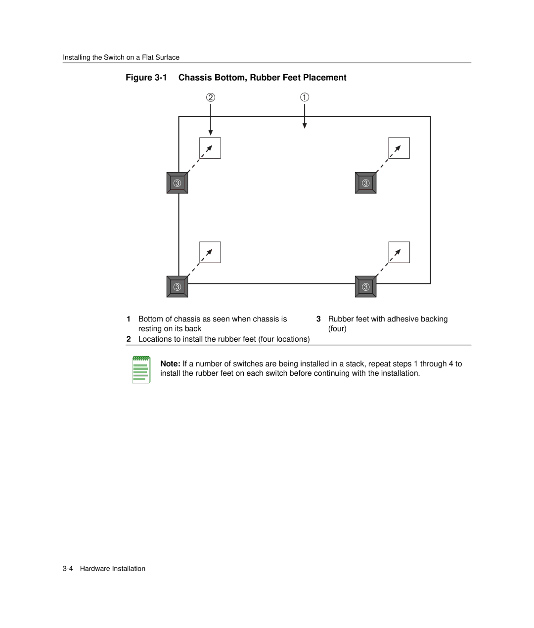
Figure 3-1 Chassis Bottom, Rubber Feet Placement
Á | À |
 |  |
 |  |
1Bottom of chassis as seen when chassis is resting on its back
2Locations to install the rubber feet (four locations)
3Rubber feet with adhesive backing (four)
Note: If a number of switches are being installed in a stack, repeat steps 1 through 4 to install the rubber feet on each switch before continuing with the installation.