Connecting AC and
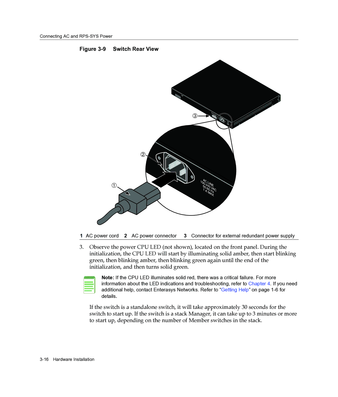
Figure 3-9 Switch Rear View
1 AC power cord 2 AC power connector 3 Connector for external redundant power supply
3.Observe the power CPU LED (not shown), located on the front panel. During the initialization, the CPU LED will start by illuminating solid amber, then start blinking green, then blinking amber, then blinking green again until the end of the initialization, and then turns solid green.
Note: If the CPU LED illuminates solid red, there was a critical failure. For more information about the LED indications and troubleshooting, refer to Chapter 4. If you need additional help, contact Enterasys Networks. Refer to “Getting Help” on page
If the switch is a standalone switch, it will take approximately 30 seconds for the switch to start up. If the switch is a stack Manager, it can take up to 3 minutes or more to start up, depending on the number of Member switches in the stack.