REASSEMBLY AND RESEALING VENT-AIR INTAKE SYSTEM
When
1
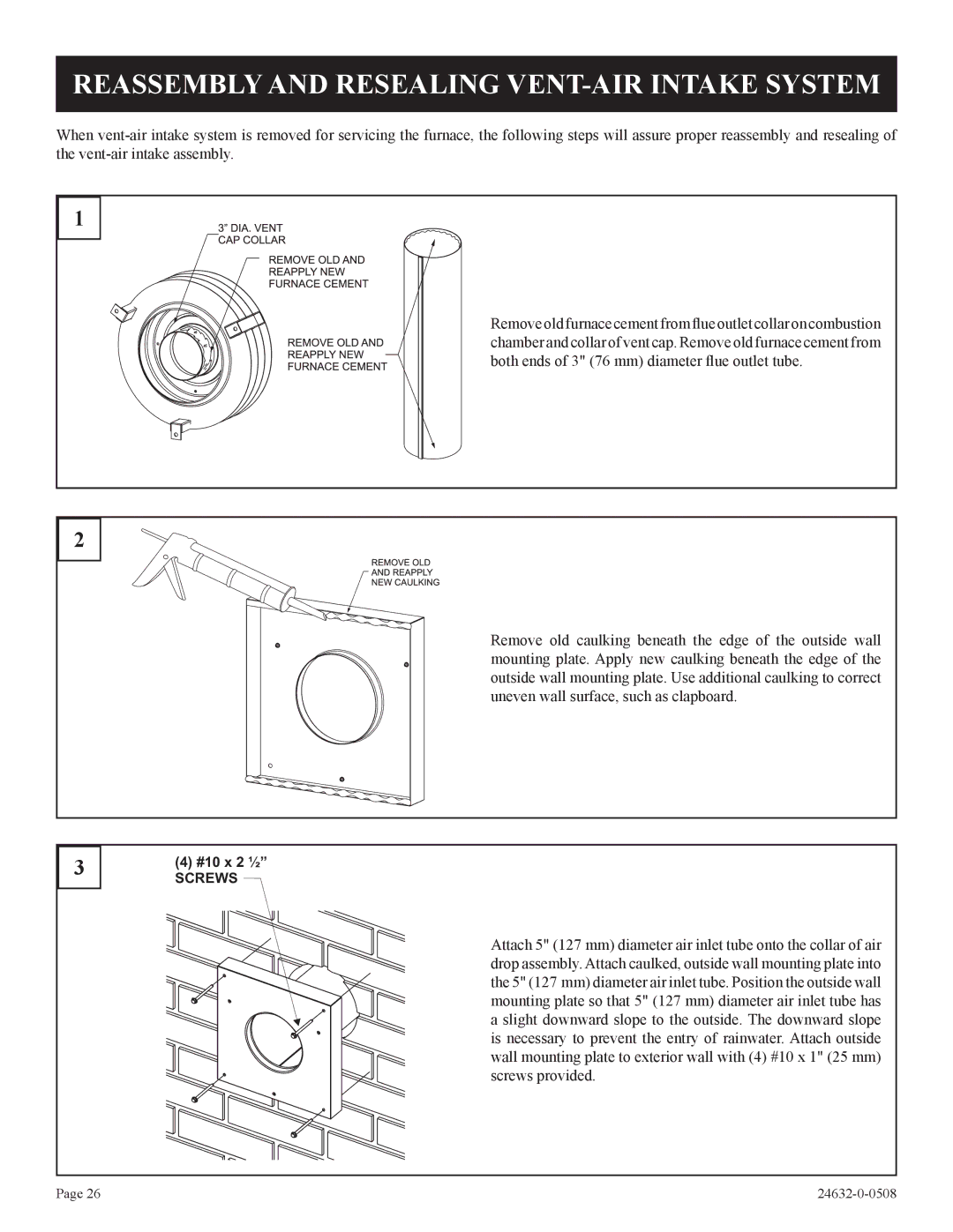
Remove old furnace cement from flue outlet collar on combustion chamber and collar of vent cap. Remove old furnace cement from both ends of 3" (76 mm) diameter flue outlet tube.
2
Remove old caulking beneath the edge of the outside wall mounting plate. Apply new caulking beneath the edge of the outside wall mounting plate. Use additional caulking to correct uneven wall surface, such as clapboard.
3
(4)#10 x 2 ½”
SCREWS
Attach 5" (127 mm) diameter air inlet tube onto the collar of air drop assembly. Attach caulked, outside wall mounting plate into the 5" (127 mm) diameter air inlet tube. Position the outside wall mounting plate so that 5" (127 mm) diameter air inlet tube has a slight downward slope to the outside. The downward slope is necessary to prevent the entry of rainwater. Attach outside wall mounting plate to exterior wall with (4) #10 x 1" (25 mm) screws provided.
Page 26 |