Plus projector families: (Code 40 hex) Plus U5, U7 (not U6xxx or Taxan)
See master Plus code list at:
Channel codes are: |
|
|
|
Computer1 | := '#SR' + 0D + 0A; | // RGB 1 | VGA |
Computer2 | := '#SA' + 0D + 0A; | // RGB 2 | VGA |
Computer3 | := '#SN' + 0D + 0A; | // Network on U7 only | |
Video1 | := '#SV' + 0D + 0A; | // Comp Video | |
Video2 | := '#SS' + 0D + 0A; | // | |
Video3 | := '#SN' + 0D + 0A; | // Network on U7 only | |
Any one of these codes can be set into Constant:0/Constant:1 for computer codes and Constant:2/Constant:3 for video codes. (The default is to have Computer1 (above) as the “Computer” channel and Video1 as the “Video” channel. Setting OPT1 switch ON will swap Video1 and Video2 channels, making
•OPT7 handshake mode and power on panel connection blink codes available;
•Turn off the
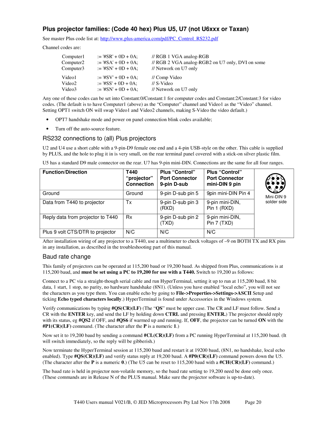
RS232 connections to (all) Plus projectors
U2 and U4 use a short cable with a
U5 has a standard D9 male connector on the rear. U7 has
Function/Direction | T440 | Plus “Control” |
| “projector” | Port Connector |
| Connection | |
|
|
|
Ground | Ground | |
|
|
|
Data from T440 to projector | Tx | |
|
| (RXD) |
Reply data from projector to T440 | Rx | |
|
| (TXD) |
|
|
|
Plus 9 volt CTS/DTR to projector | N/C | N/C |
|
|
|
Plus “Control” Port Connector mini-DIN 9 pin
9pin
N/C
12
3 4 5 6
7 8 9
After installation wiring of any projector to a T440, use a multimeter to check voltages of
Baud rate change
This family of projectors can be operated at 115,200 baud or 19,200 baud. As shipped from Plus, communications is at
115,200 baud, and must be set using a PC to 19,200 for use with a T440. Switch to 19,200 as follows:
Connect to a PC via a
Verify communications by typing #QS(CR)(LF) (The “QS” must be upper case. The CR and LF must follow. Send a CR with the ENTER key, and send the LF by holding down CTRL and pressing ENTER.) The projector should reply with its status, eg #QS2 if OFF, and #QS6 if warmed up and running. If, OFF, the projector can be turned ON with the #P1(CR)(LF) command. (The character after the P is a numeric 1.)
Now set it to 19,200 baud by sending a command #CL(CR)(LF) from a PC running HyperTerminal at 115,200 baud. (It will switch immediately, so the reply will be gibberish.)
Now terminate the HyperTerminal session at 115,200 baud and restart it at 19200 baud, (8N1, no handshake, local echo enabled). Type #QS(CR)(LF) and verify status reply at 19,200 baud. A #P0(CR)(LF) command powers down the U5. (The character after the P is a numeric 0.) (The U5 can be reset to 115,200 baud with a #CH(CR)(LF) command.)
The baud rate is held in projector
T440 Users manual V021/B, © JED Microprocessors Pty Ltd Nov 17th 2008 | Page 20 |
