Hitachi projectors (Code 44 hex, single audio control, Code 45, “by channel” audio)
This family has a compact set of “BE EF” hex commands consistent across the models. Two code groups are provided:
Code 44 is used when there is an audio in for typically each RGB channel but one audio shared by all video inputs. There is only one pair of commands for audio Inc/Dec and the level of all channels is controlled by this one pair of commands. So if a level has been dropped for a RGB channel, the audio level is down for the Video input and needs to be manually adjusted up. These are typically many older models (excluding
Also supported by code 44 are:
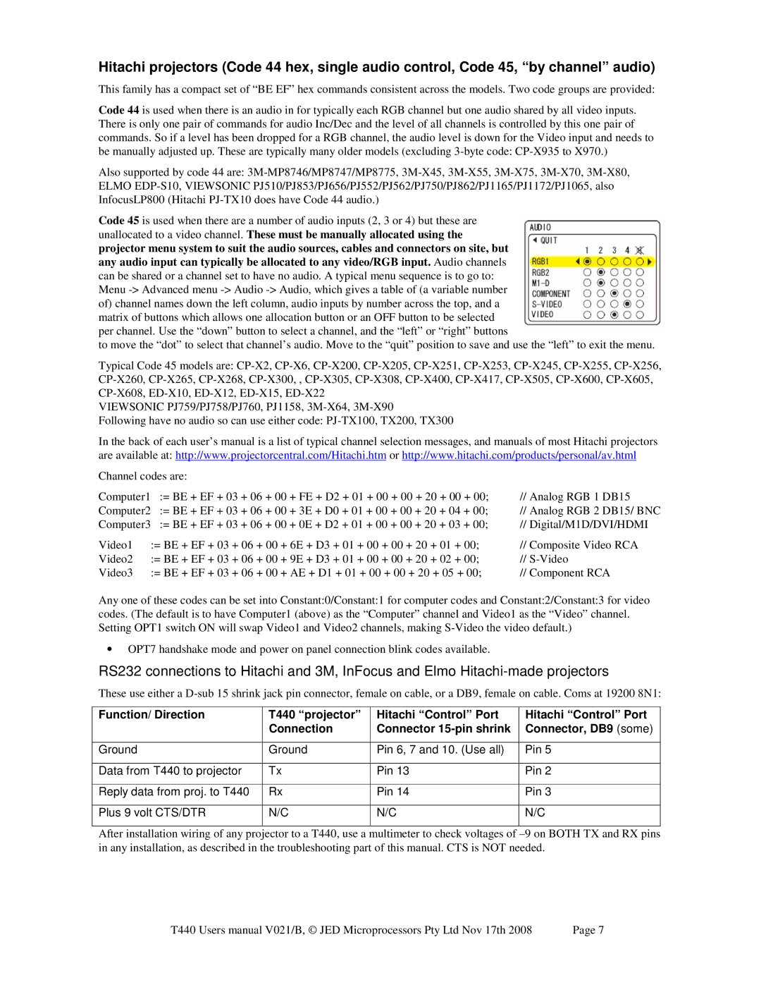
Code 45 is used when there are a number of audio inputs (2, 3 or 4) but these are unallocated to a video channel. These must be manually allocated using the projector menu system to suit the audio sources, cables and connectors on site, but any audio input can typically be allocated to any video/RGB input. Audio channels can be shared or a channel set to have no audio. A typical menu sequence is to go to: Menu
to move the “dot” to select that channel’s audio. Move to the “quit” position to save and use the “left” to exit the menu.
Typical Code 45 models are:
VIEWSONIC PJ759/PJ758/PJ760, PJ1158,
Following have no audio so can use either code:
In the back of each user’s manual is a list of typical channel selection messages, and manuals of most Hitachi projectors are available at: http://www.projectorcentral.com/Hitachi.htm or http://www.hitachi.com/products/personal/av.html
Channel codes are: |
| |
Computer1 | := BE + EF + 03 + 06 + 00 + FE + D2 + 01 + 00 + 00 + 20 + 00 + 00; | // Analog RGB 1 DB15 |
Computer2 | := BE + EF + 03 + 06 + 00 + 3E + D0 + 01 + 00 + 00 + 20 + 04 + 00; | // Analog RGB 2 DB15/ BNC |
Computer3 | := BE + EF + 03 + 06 + 00 + 0E + D2 + 01 + 00 + 00 + 20 + 03 + 00; | // Digital/M1D/DVI/HDMI |
Video1 | := BE + EF + 03 | + 06 | + 00 | + 6E + D3 + 01 + 00 + 00 + 20 + 01 + 00; | // Composite Video RCA |
Video2 | := BE + EF + 03 | + 06 | + 00 | + 9E + D3 + 01 + 00 + 00 + 20 + 02 + 00; | // |
Video3 | := BE + EF + 03 | + 06 | + 00 | + AE + D1 + 01 + 00 + 00 + 20 + 05 + 00; | // Component RCA |
Any one of these codes can be set into Constant:0/Constant:1 for computer codes and Constant:2/Constant:3 for video codes. (The default is to have Computer1 (above) as the “Computer” channel and Video1 as the “Video” channel. Setting OPT1 switch ON will swap Video1 and Video2 channels, making
•OPT7 handshake mode and power on panel connection blink codes available.
RS232 connections to Hitachi and 3M, InFocus and Elmo
These use either a
Function/ Direction
Ground
Data from T440 to projector
Reply data from proj. to T440
Plus 9 volt CTS/DTR
T440 “projector” Connection
Ground
Tx
Rx
N/C
Hitachi “Control” Port Connector
Pin 6, 7 and 10. (Use all)
Pin 13
Pin 14
N/C
Hitachi “Control” Port Connector, DB9 (some)
Pin 5
Pin 2
Pin 3
N/C
After installation wiring of any projector to a T440, use a multimeter to check voltages of
T440 Users manual V021/B, © JED Microprocessors Pty Ltd Nov 17th 2008 | Page 7 |