NEC LCD: 3000/3210/4000/4010/4020/4610/4620/5220/5710/6520P/L, SC40/SC46,
NEC LCD: M40/M46 Old T1, Old T2, Multeos (new mode),
NEC Plasma: 42XC10/42XP10, 50XC10/50XP10, 60XC10/60XP10
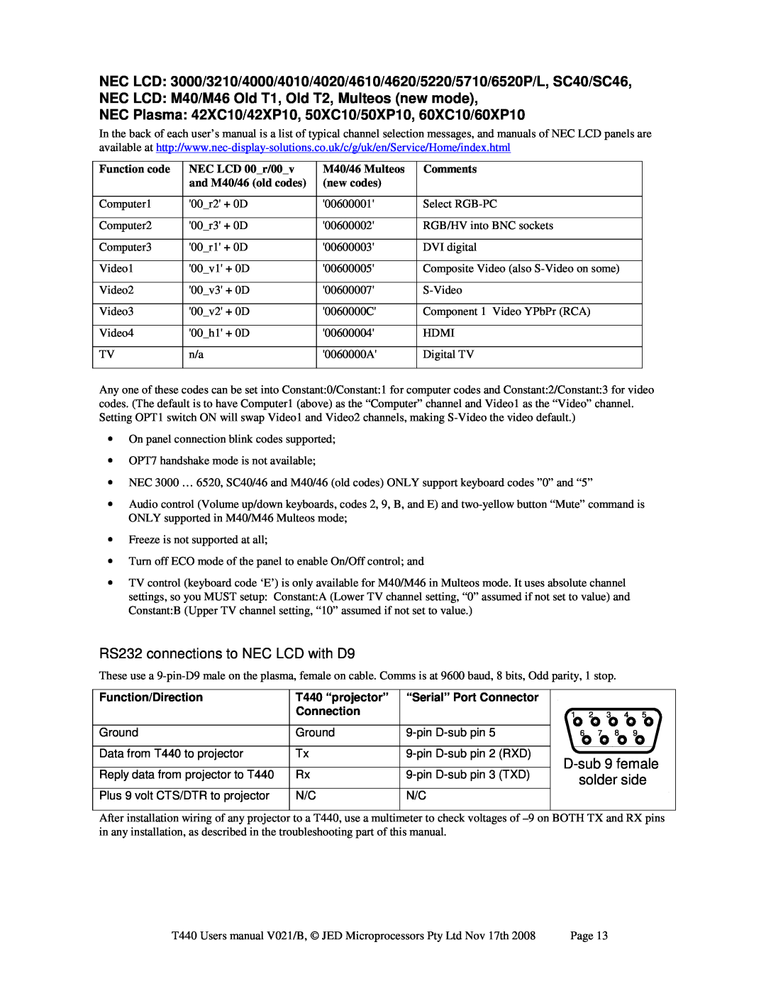
In the back of each user’s manual is a list of typical channel selection messages, and manuals of NEC LCD panels are available at
Function code | NEC LCD 00_r/00_v | M40/46 Multeos | Comments |
| and M40/46 (old codes) | (new codes) |
|
|
|
|
|
Computer1 | '00_r2' + 0D | '00600001' | Select |
|
|
|
|
Computer2 | '00_r3' + 0D | '00600002' | RGB/HV into BNC sockets |
|
|
|
|
Computer3 | '00_r1' + 0D | '00600003' | DVI digital |
|
|
|
|
Video1 | '00_v1' + 0D | '00600005' | Composite Video (also |
|
|
|
|
Video2 | '00_v3' + 0D | '00600007' | |
|
|
|
|
Video3 | '00_v2' + 0D | '0060000C' | Component 1 Video YPbPr (RCA) |
|
|
|
|
Video4 | '00_h1' + 0D | '00600004' | HDMI |
|
|
|
|
TV | n/a | '0060000A' | Digital TV |
|
|
|
|
Any one of these codes can be set into Constant:0/Constant:1 for computer codes and Constant:2/Constant:3 for video codes. (The default is to have Computer1 (above) as the “Computer” channel and Video1 as the “Video” channel. Setting OPT1 switch ON will swap Video1 and Video2 channels, making
•On panel connection blink codes supported;
•OPT7 handshake mode is not available;
•NEC 3000 … 6520, SC40/46 and M40/46 (old codes) ONLY support keyboard codes ”0” and “5”
•Audio control (Volume up/down keyboards, codes 2, 9, B, and E) and
•Freeze is not supported at all;
•Turn off ECO mode of the panel to enable On/Off control; and
•TV control (keyboard code ‘E’) is only available for M40/M46 in Multeos mode. It uses absolute channel settings, so you MUST setup: Constant:A (Lower TV channel setting, “0” assumed if not set to value) and Constant:B (Upper TV channel setting, “10” assumed if not set to value.)
RS232 connections to NEC LCD with D9
These use a
Function/Direction | T440 “projector” | “Serial” Port Connector |
|
|
| ||
| Connection |
|
| 1 2 | 3 | 4 5 | |
Ground | Ground |
| 6 | 7 8 | 9 | ||
Data from T440 to projector | Tx | (RXD) |
| ||||
Reply data from projector to T440 | Rx | (TXD) | |||||
solder side | |||||||
|
|
|
| ||||
Plus 9 volt CTS/DTR to projector | N/C | N/C |
|
|
|
| |
After installation wiring of any projector to a T440, use a multimeter to check voltages of
T440 Users manual V021/B, © JED Microprocessors Pty Ltd Nov 17th 2008 | Page 13 |
