Epson VP21 projectors (Code 0C hex)
This family has many members with a range of channel messages.
Typical models are: EMP 30/52/53/54/61/73/74/81/62/82/83/400W/600/800/810/811/820/821/822/828/830/835/830 / EMP 6100/6000/6110/1810/1815/1825/7800/7850/7900/7950/8300/9300/S1/S1H
In the back of each user’s manual is a list of typical channel selection messages,
Channel codes are: |
|
Computer1 | := 'SOURCE 11' + 0D; |
Computer2 | := 'SOURCE 21' + 0D; |
Computer3 | := 'SOURCE 30' + 0D; |
Computer4 | := 'SOURCE 31' + 0D; |
Computer5 | := 'SOURCE B1' + 0D; |
Video1 | := 'SOURCE 41' + 0D; |
Video2 | := 'SOURCE 42' + 0D; |
Video3 | := 'SOURCE 14' + 0D; |
Video4 | := 'SOURCE 24' + 0D; |
Video5 | := 'SOURCE 15' + 0D; |
Video6 | := 'SOURCE 25' + 0D; |
Video7 | := 'SOURCE 30' + 0D; |
Video8 | := 'SOURCE 31' + 0D; |
Video9 | := 'SOURCE B2' + 0D; |
Video10 | := 'SOURCE B3' + 0D; |
Video11 | := 'SOURCE B4' + 0D; |
Video12 | := 'SOURCE C4' + 0D; |
Video13 | := 'SOURCE C5' + 0D; |
//DSUB1 VGA
//DSUB2 VGA
//INPUT3 DVI-D
//INPUT3 D-RGB
//INPUT4 BNC
//Comp Video
//
//Component on DSUB1 or YCbCr on DSUB1
//Component on DSUB2 or YCbCr on DSUB2
//YCbCr on DSUB1
//YCbCr on DSUB2
//INPUT3
//INPUT3
//INPUT4 BNC COMPONENT
//INPUT4 BNC COMPONENT YCbCr
//INPUT4 BNC COMPONENT YPbPr
//INPUT5 BNC COMPONENT YCbCr
//INPUT5 BNC COMPONENT YPbPr
Any one of these codes can be set into Constant:0/Constant:1 for computer codes and Constant:2/Constant:3 for video codes. (The default is to have Computer1 (above) as the “Computer” channel and Video1 as the “Video” channel. Setting OPT1 switch ON will swap Video1 and Video2 channels, making
•OPT7 handshake mode and power on panel connection blink codes available.
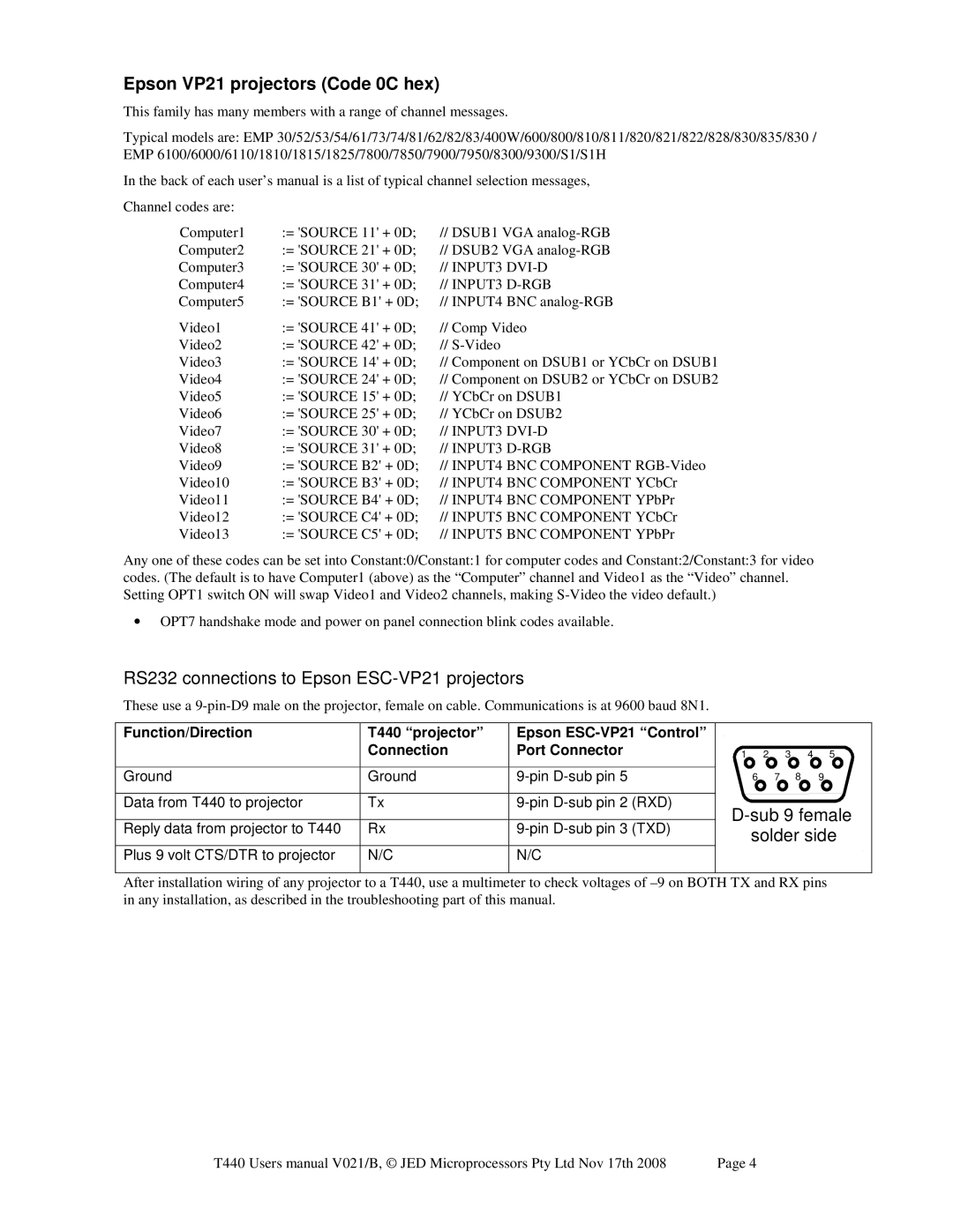
RS232 connections to Epson ESC-VP21 projectors
These use a
Function/Direction | T440 “projector” | Epson |
| Connection | Port Connector |
|
|
|
Ground | Ground | |
|
|
|
Data from T440 to projector | Tx | |
|
|
|
Reply data from projector to T440 | Rx | |
|
|
|
Plus 9 volt CTS/DTR to projector | N/C | N/C |
|
|
|
1 2 3 4 5
6 7 8 9
D-sub 9 female solder side
After installation wiring of any projector to a T440, use a multimeter to check voltages of
T440 Users manual V021/B, © JED Microprocessors Pty Ltd Nov 17th 2008 | Page 4 |