2.MAKING REPAIRS TO THE REFRIGERATING SYSTEM

2.1.Opening the Refrigerating System with Refrige- rant R600a (Isobutane) for Repairs

The Possibility of Fire/Explosion exists

Therefore, it is important to pay attention to the following points before commencing repairs of the refrigerating system:

1.The serviceman is familiar with the dangers related to combustible refrigerants and knows how to use the per- sonal protection equipment.

2.There is no risk of sparks forming near the workroom.

3.Do not smoke or use naked flame or other means of heat. Therefore, no soldering on the system is allowed.

4.Electrical appliances to be used during the service must not produce sparks.

5.See that there is good ventilation in the workroom.

6.Do not let the refrigerant flow into basement openings, low lying rooms, sewer systems, etc. as R600a is heavier than air.

7.Safety rules for handling, storage and transport of com- bustible refrigerant applicable in the various countries must be followed.

If a hermetic refrigerating system is to function correctly and have a reasonably long life, it is essential that the number of impurities present in the system i.e. moisture, foreign gases, dirt, etc. is kept at a minimum.

This fact must be taken into consideration when repairs are to be made, and the necessary precautions must be taken.

If there is any risk at all of finding refrigerant near or inside the cooling/freezing unit, it must be found before commencing the repairs. Note that some leak detectors must not be switched on in the workroom.

Before commencing repairs, make sure that an exact diagno- sis of the problem has been made.

Mount a service valve or drilling tongs on the charging pipe (process pipe) and confirm the diagnosis with a suction ma- nometer. Close the valve.

First Evacuation

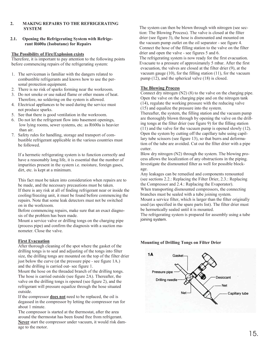
After thorough cleaning of the spot where the gasket of the drilling tongs is to seal and adjusting of the tongs into filter size, the drilling tongs are mounted on the top of the filter drier just below the curve (at the pressure pipe - see figure 1A.) and the drilling is carried out- see figure 1.

Mount the hose on the threaded branch of the drilling tongs. The hose is carried outside (see figure 2A). Thereafter, the valve on the drilling tongs is opened (see figure 2), and the refrigerant will pressure equalize through the hose situated outside.

If the compressor does not need to be replaced, the oil is degassed in the compressor by letting the compressor run for about 1 minute.

The compressor is started at the thermostat, after the area around the thermostat has been found free from refrigerant. Never start the compressor under vacuum, it would risk dam- age to the motor.

The system can then be blown through with nitrogen (see sec- tion: The Blowing Process). The valve is closed at the filter drier (see figure 3), the hose is dismounted and mounted on the vacuum pump outlet on the oil separator - see figure 4. Connect the hose of the filling station to the valve on the filter drier and open the valve - see figures 5 and 6.

The refrigerating system is now ready for the first evacuation. Evacuate to a pressure of approximately 5 mbar. After the first evacuation, the valves are closed at the filter drier (9), at the vacuum gauge (10), for the filling station (11), for the vacuum pump (12), and the spherical valve (18) is closed.

The Blowing Process

Connect dry nitrogen (N2) (8) to the valve on the charging pipe. Open the valve on the charging pipe and on the nitrogen tank (14), regulate the working pressure with the reducing valve (15) and equalize the pressure into the system.

Thereafter, the system, the filling station and the vacuum pump are thoroughly blown through by opening the valve on the drill- ing tongs at the filter drier (see figure 9) for the filling station

(11)and the valve for the vacuum pump is opened slowly (12). Open the system by cutting off the capillary tube using capil- lary tube scissors (see figure 13), so that burrs and deforma- tion of the tube are avoided. Cut out the filter drier with a pipe cutter.

Blow dry nitrogen (N2) through the system. The blowing pro- cess allows the localization of any obstructions in the piping. Investigate the dismounted filter as well for possible block- age.

Any leakages can be remedied and components remounted (see sections 2.2.: Replacing the Filter Drier, 2.3.: Replacing the Compressor and 2.4.: Replacing the Evaporator).

When transporting dismounted compressors, the connecting branches must be sealed with a tube joining system.

Mount a service filter, which is larger than the filter originally used (as specified in the spare parts list). The filter drier must be hermetically sealed until it is mounted.

The refrigerating system is prepared for assembly using a tube joining system.

Mounting of Drilling Tongs on Filter Drier

15.

Page 17
Image 17
Equator 375 service manual First Evacuation, Blowing Process, Mounting of Drilling Tongs on Filter Drier

375 specifications

Equator 375 is a state-of-the-art maritime vessel that has garnered significant attention in the shipping and logistics industry due to its innovative design and advanced technologies. This vessel is specifically engineered to meet the growing demands of global trade while minimizing environmental impact.

One of the standout features of the Equator 375 is its impressive cargo capacity. With a deadweight tonnage of 37,500 tons, this vessel can accommodate a wide variety of cargo types, including bulk goods, containers, and project cargo. Its versatile design makes it suitable for multiple shipping routes, enhancing operational efficiency and reducing transit times.

Equator 375 is equipped with cutting-edge propulsion technology. It utilizes a dual-fuel engine that can run on both heavy fuel oil and liquefied natural gas (LNG). This flexibility allows the vessel to operate more sustainably, significantly reducing greenhouse gas emissions and complying with international regulations. By adopting LNG as a fuel source, the Equator 375 contributes to a cleaner maritime environment, helping to meet stringent emission targets.

In terms of navigation, the vessel features an advanced integrated bridge system that enhances operational safety and efficiency. The system includes state-of-the-art radar, automatic identification systems (AIS), and electronic chart display systems (ECDIS). These technologies ensure that crew members have access to real-time data, improving situational awareness and decision-making during voyages.

Equator 375 also prioritizes crew comfort and safety. The living quarters are designed ergonomically, with modern amenities to provide a comfortable environment for the crew during long voyages. Safety equipment is installed throughout the vessel, including fire suppression systems and life-saving appliances, ensuring that crew members are protected in case of emergencies.

Moreover, the vessel is designed with an eco-friendly hull shape, reducing water resistance and optimizing fuel efficiency. This hydrodynamic design contributes to lower operating costs, making Equator 375 not only a technologically advanced vessel but also a cost-effective option for shipping companies.

In summary, the Equator 375 is a remarkable addition to the maritime fleet, featuring impressive cargo capacity, advanced propulsion technology, and a focus on crew comfort and safety. Its eco-friendly design and innovative navigation systems position it as a leader in sustainable maritime transportation, paving the way for the future of shipping.