Cabling
Each interface can connect to the computer or workstation’s local monitor and to a projector or other display device.
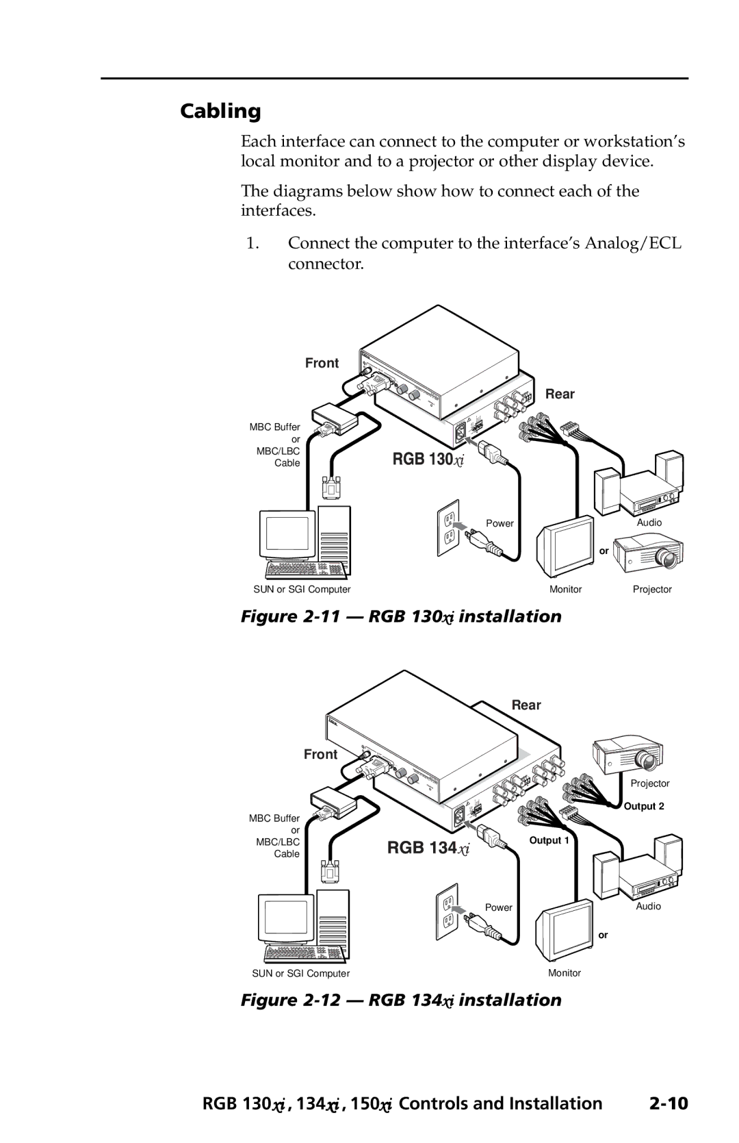
The diagrams below show how to connect each of the interfaces.
1.Connect the computer to the interface’s Analog/ECL connector.
Front
MBC Buffer
or
MBC/LBC
Cable
AUDIO
INPUT
MBC |
H. | UNIVERSAL |
|
|
| Rear |
POWER | H.SHIFT | W | /ADSPxi |
| |
SHIFT |
| INTERFACERGB | 130 |
|
|
|
| MIN/MAX |
|
| |
|
|
| SOGOUT | DDSP SERR SPARE | OUTPUT |
|
|
|
| ||
Power | Audio |
or ![]()
SUN or SGI Computer | Monitor | Projector |
Figure 2-11 — RGB 130xi installation
Rear
Front
MBC Buffer
or
MBC/LBC
Cable
AUDIO
INPUT
MBC |
POWER
H. | SHIFT | UNIVERSAL |
| RGB |
|
|
| H. | INTERFACE W | 134 xi | |
|
| SHIFT | M |
| /ADSP |
|
|
|
| IN/MAX | |
SOGOUT DDSP SERR SPARE
Projector
OUTPUT
Output 2
Output 1
Power | Audio |
| or |
SUN or SGI Computer | Monitor |
Figure 2-12 — RGB 134xi installation
RGB 130xi , 134xi , 150xi Controls and Installation |