Controls and Installation, cont’d
RGB 134xi front panel features
RGB 134![]()
| INPUTS | UNIVERSAL INTERFACE W/ADSP |
AUDIO | ANALOG/ECL |
|
| MBC | MIN/MAX |
|
| |
| H. SHIFT | V. SHIFT |
| POWER |
|
1 | 2 | 3 | 4 | 5 | 6 | 7 |
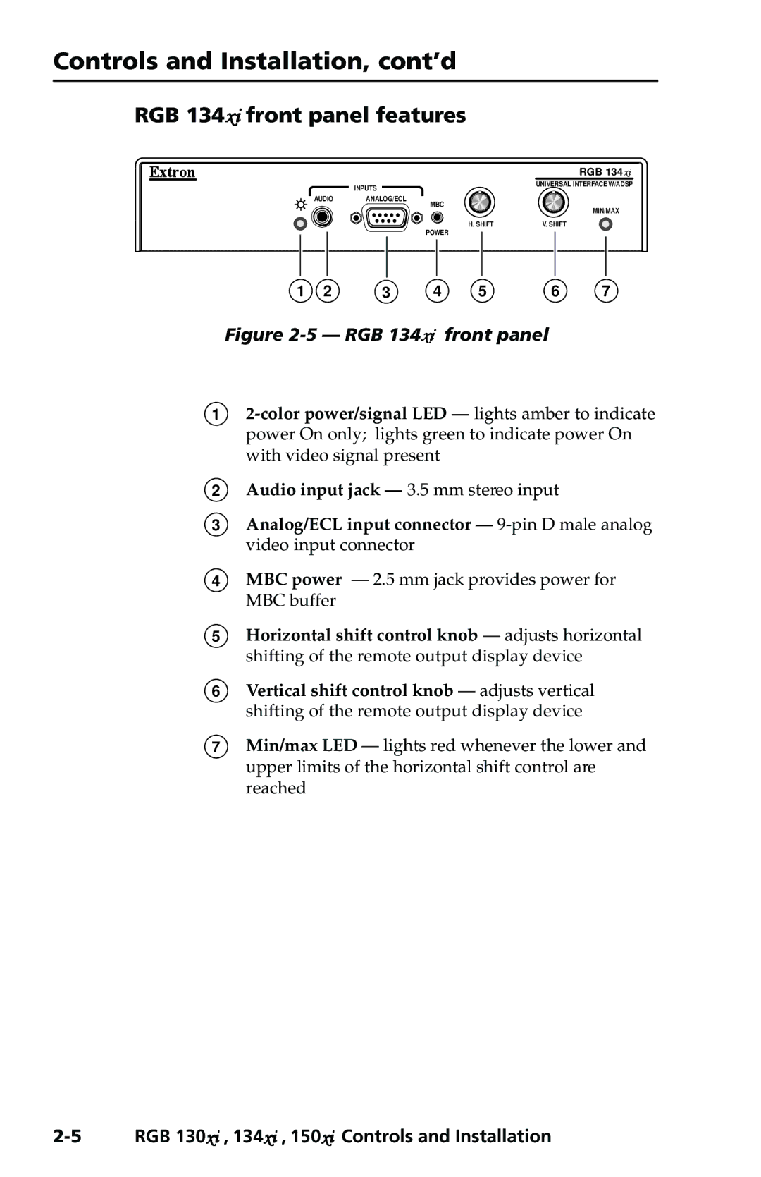
Figure 2-5 — RGB 134xi front panel
1
2Audio input jack — 3.5 mm stereo input
3Analog/ECL input connector —
4MBC power — 2.5 mm jack provides power for MBC buffer
5Horizontal shift control knob — adjusts horizontal shifting of the remote output display device
6Vertical shift control knob — adjusts vertical shifting of the remote output display device
7Min/max LED — lights red whenever the lower and upper limits of the horizontal shift control are reached