Controls and Installation, cont’d
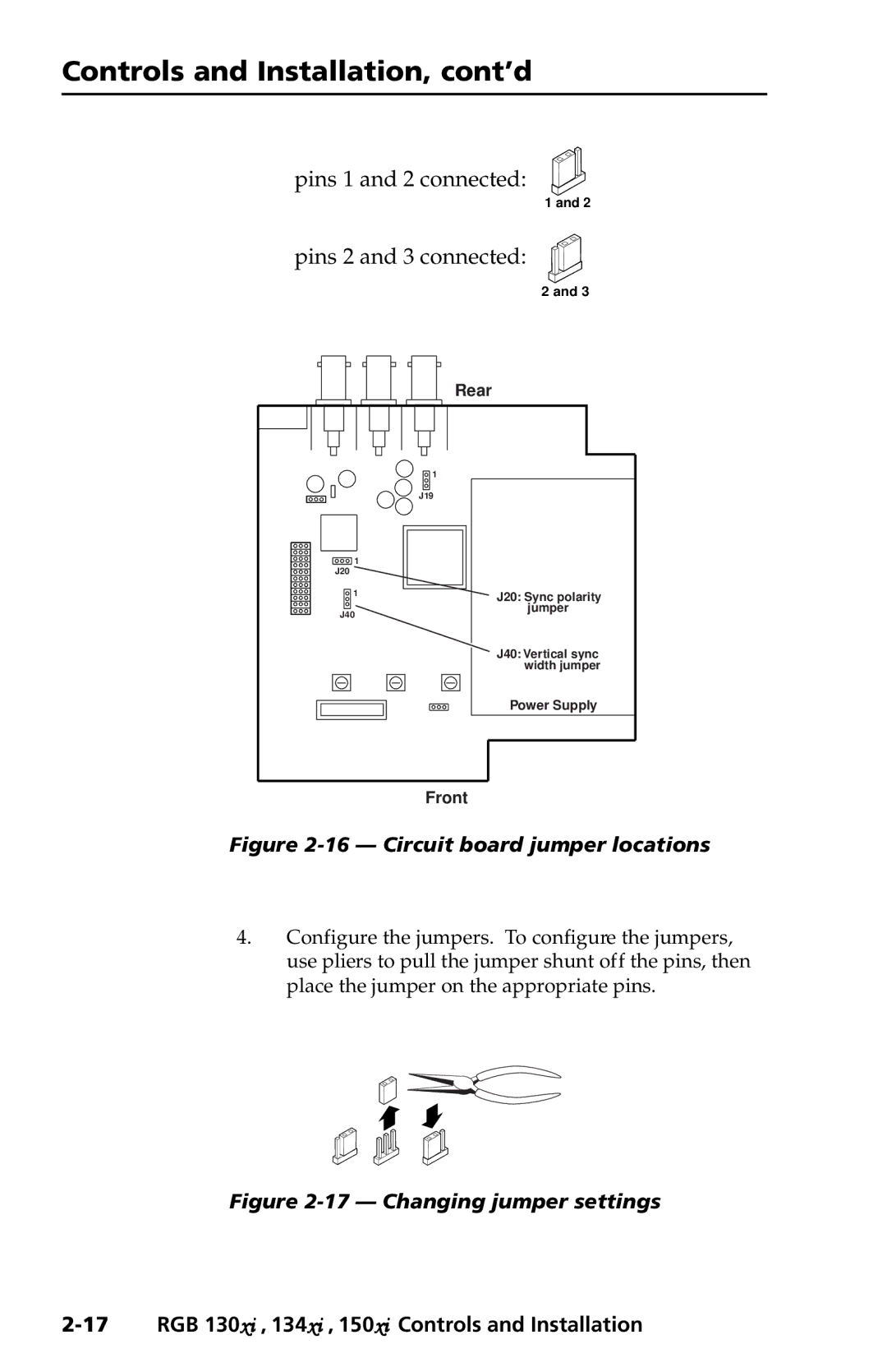
pins 1 and 2 connected:
| 1 and 2 |
pins 2 and 3 connected: | |
| 2 and 3 |
| Rear |
| 1 |
| J19 |
1 |
|
J20 |
|
1 | J20: Sync polarity |
J40 | jumper |
| |
| J40: Vertical sync |
| width jumper |
| Power Supply |
| Front |
Figure 2-16 — Circuit board jumper locations
4.Configure the jumpers. To configure the jumpers, use pliers to pull the jumper shunt off the pins, then place the jumper on the appropriate pins.