RGB 134xi rear panel features
| R | G | B | |
|
| |||
GAIN/ | SOG DDSP SERR SPARE | H | V | S |
PEAK | ||||
100% |
|
|
|
|
UNITY |
|
|
|
|
50% |
|
| OUTPUT 1 |
|
50/60 Hz |
|
|
|
R ![]() G
G ![]() B
B
HVS
OUTPUT 2
1 | 2 | 3 | 4 | 5 | 6 |
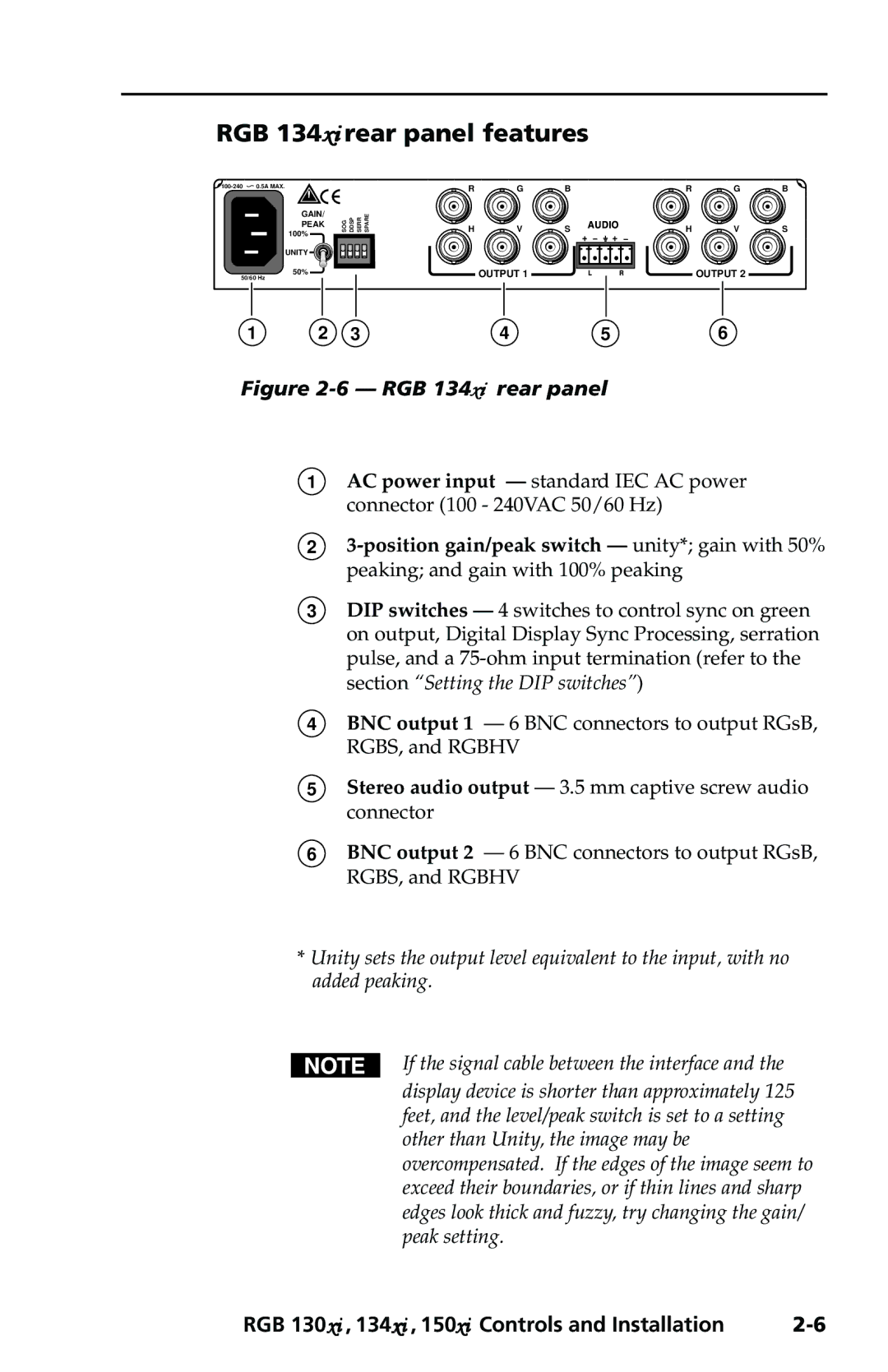
Figure 2-6 — RGB 134xi rear panel
1AC power input — standard IEC AC power connector (100 - 240VAC 50/60 Hz)
2
3DIP switches — 4 switches to control sync on green on output, Digital Display Sync Processing, serration pulse, and a
4BNC output 1 — 6 BNC connectors to output RGsB, RGBS, and RGBHV
5Stereo audio output — 3.5 mm captive screw audio connector
6BNC output 2 — 6 BNC connectors to output RGsB, RGBS, and RGBHV
*Unity sets the output level equivalent to the input, with no added peaking.
If the signal cable between the interface and the display device is shorter than approximately 125 feet, and the level/peak switch is set to a setting other than Unity, the image may be overcompensated. If the edges of the image seem to exceed their boundaries, or if thin lines and sharp edges look thick and fuzzy, try changing the gain/ peak setting.
RGB 130xi , 134xi , 150xi Controls and Installation |