a. If one or more output LEDs are lit AND the +dB LED is lit, press and release the < button repeatedly until the highest-numbered lit output LED goes out. Count the button presses. In example 8, assume a value of +8 dB. It will take three presses of the < button for the Output 1 LED to go out.

If one or more output LEDs are lit AND the –dB LED is lit, press and release the > button repeatedly until the highest-numbered lit output LED goes out. Count the button presses.

If the +dB LED is lit and NO output LEDs are lit, press and release the

<button repeatedly until the +dB and –dB LED are both lit, indicating

0 dB. Count the button presses.

If the –dB LED is lit and NO output LEDs are lit, press and release the

>button repeatedly until the +dB and –dB LED are both lit, indicating

0 dB. Count the button presses.

b. Return to the original audio gain setting by pressing and releasing the < or > button (the opposite of the button you pressed in step a) the same number of steps you pressed the opposite arrow button in step 1. In example 8, this means pressing the > button three times.

c. Add the dB value indicated by the highest-numbered lit output LED (no output LEDs lit and both dB LEDs lit = 0 dB) and either of the following:

The number of button presses from 0 dB, or

The number of button presses from when the highest-numbered output LED lit. In example 8:

Output 1 LED:

6 dB

+ 2 presses:

+2 dB


8 dB

d. The lit +dB or –dB LED indicates the gain (+) or attenuation (–).

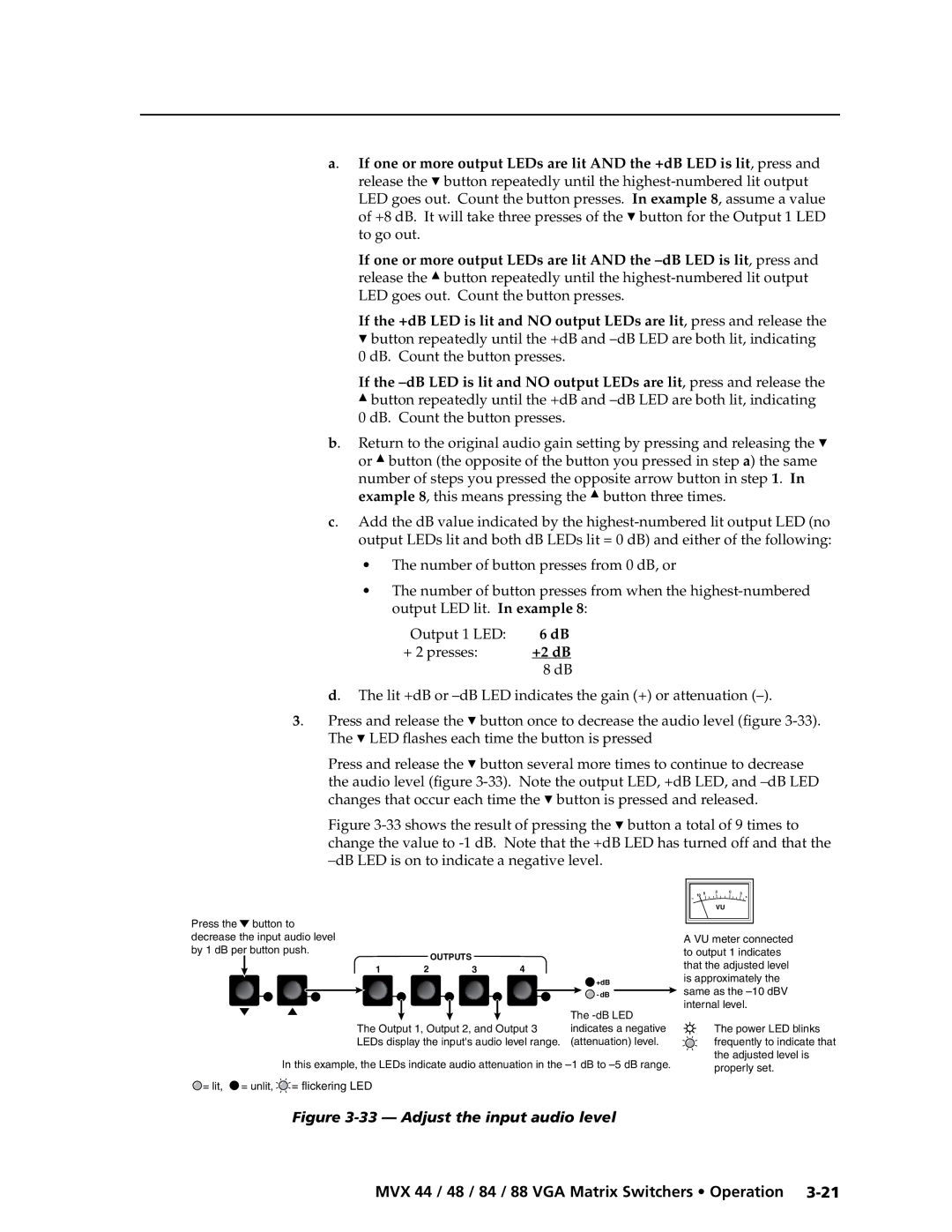
3. Press and release the < button once to decrease the audio level (figure 3-33). The < LED flashes each time the button is pressed

Press and release the < button several more times to continue to decrease the audio level (figure 3-33). Note the output LED, +dB LED, and –dB LED changes that occur each time the < button is pressed and released.

Figure 3-33 shows the result of pressing the < button a total of 9 times to change the value to -1 dB. Note that the +dB LED has turned off and that the –dB LED is on to indicate a negative level.

PRELIMINARY

Press the button to


decrease the input audio level


by 1 dB per button push.


OUTPUTS


1

2

3

4


+dB


-dB


The -dB LED

The Output 1, Output 2, and Output 3

indicates a negative

LEDs display the input's audio level range. (attenuation) level.

In this example, the LEDs indicate audio attenuation in the –1 dB to –5 dB range.

= lit, = unlit, = flickering LED

10

6

3

0

3

+


VU


A VU meter connected to output 1 indicates that the adjusted level is approximately the same as the –10 dBV internal level.

The power LED blinks frequently to indicate that the adjusted level is properly set.

Figure 3-33 — Adjust the input audio level

MVX 44 / 48 / 84 / 88 VGA Matrix Switchers • Operation 3-21

Page 39
Image 39
Extron electronic MVX 88 Series manual Output 1 LED + 2 presses, +2 dB

MVX 88 Series specifications

The Extron MVX 88 Series is a cutting-edge technology solution designed to facilitate seamless audio and video signal routing in a variety of settings, from educational institutions to corporate environments. This versatile matrix switcher series supports the demanding needs required for high-performance AV distribution.

One of the key features of the MVX 88 Series is its ability to handle multiple input and output formats, including HDMI, VGA, and composite video, ensuring versatility in connecting various devices. It supports resolutions up to 1920x1200 at 60 Hz, providing crystal-clear image quality. The series 8x8 matrix switcher allows users to route any input to any output, offering maximum flexibility in AV configurations. This means that users can easily switch between multiple sources without the need for complex wiring.

Another notable characteristic of the MVX 88 Series is its integrated scaling capabilities. Each output has a built-in video scaler that adjusts the input signal to match the required resolution of the display device. This technology enhances viewing experiences by eliminating compatibility issues, making it easier to connect different devices and ensuring optimal picture clarity.

The Extron MVX 88 Series also boasts advanced audio functionality. It features a built-in audio router and supports various audio formats, allowing users to manage audio signals alongside video. This capability is crucial for applications where synchronized audio and video output is essential, such as presentations and video conferences.

In terms of control, the MVX 88 Series is designed for ease of use. It includes an intuitive front panel interface, allowing users to quickly select inputs and outputs. Additionally, it supports various external control options, including RS-232 and Ethernet, making it compatible with a wide range of control systems. This adaptability simplifies integration into existing AV setups.

Durability and reliability are critical aspects of the MVX 88 Series. It is built to withstand rigorous daily use, featuring a robust enclosure that protects the internal components. Furthermore, Extron's commitment to quality ensures that users can depend on the MVX 88 for consistent performance in all applications.

Overall, the Extron MVX 88 Series stands out in the realm of AV matrix switchers, offering remarkable features, advanced technologies, and user-friendly characteristics that meet the demands of modern AV environments. Whether for classrooms, conference rooms, or control centers, the MVX 88 Series is an ideal solution for comprehensive audio and video management.