Contents
RGB 201 Rxi
Universal Video Interface with Audio
Precautions
安全须知 中文
FCC Class a Notice
Page
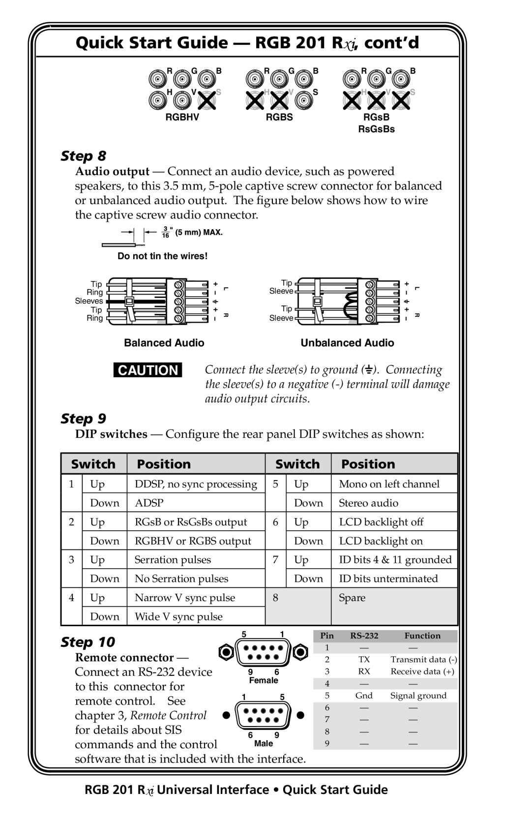
Quick Start Guide RGB 201 Rxi
RGB 201 Rxi Universal Interface Quick Start Guide
Remote control. See
Switch Position
Connect an RS-232 device To this connector for
For details about SIS Commands and the control
Table of Contents
Table of Contents, cont’d
One
Introductionduction,cont’d About this Manual
About the RGB 201 Rxi
RGB 201 Rxi Universal Interface Introduction
Features
RGB 201 R xi Universal Interface Introduction
Introduction, cont’d
Two
Instaltal lationandandOperation,cont’d Installation Overview
RGB 201 Rxi Universal Interface Installation and Operation
Internal Configuration
RGB 201 Rxi Universal Interface Installation and Operation
Installation and Operation, cont’d
Sync polarity jumpers
Internal sync DIP switches RsGsBs
RGB 201 R xi Universal Interface Installation and Operation
Video clamping jumper
Installation and Operation, cont’d Mounting the Interface
Tabletop placement
Under-desk mounting
Through-desk mounting
Through-desk mounting
Installation and Operation, cont’d
Rack mounting procedure
Rack mounting
UL guidelines for rack mounting
Rack mounting
Rear Panel Connections and Switches
Pin HD female connector
Audio output connector Connect an audio
Connect the cables to five BNCs
Ddsp
Spare
Remote connector pinout
Front panel controls and indicators
Centering controls
Many projectors store centering information in their own
LCD screen backlight
Centering memory
LCD display
Scan rate indication
Troubleshooting
If the image does not appear or there is no sound
If the image is not displayed correctly
If the interface does not respond to controls
If the image is not correctly centered
Three
Simple Instruction Set Control
RGB 201 Rxi Universal Interface Remote Control
RemoteControl,cont’d
Host-to-interface communications
Using the command/response table
Error responses
Timeout
Symbol definitions
Command/response table for SIS commands
Remote
RGB 201 R xi Universal Interface Remote Control
Installing the software
Using the software
Control Software for Windows
Remote Control, cont’d
Using the help system
AAppendix
Video input
ReferencerenceInformation,cont’d Specifications
Video
Video output
Audio output
Audio
Audio input
Control/remote interface
General
Reference Information, cont’d
Included Parts
Included Parts Part number
Cables
Optional Accessories
Accessories Part number
Adapter cables with Audio Part number
BNC cables Part number
Extron’s Warranty
USA, Canada, South America Japan Central America
Extron Electronics. All rights reserved