PROGRAM FUNCTIONS
ALARMS
Alarm Setup on PC
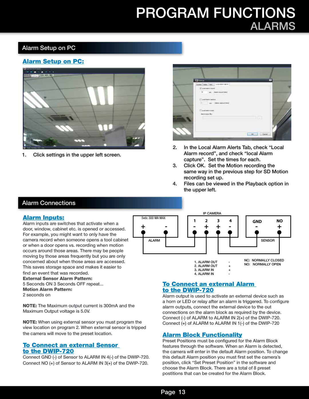
Alarm Setup on PC:
1.Click settings in the upper left screen.
2.In the Local Alarm Alerts Tab, check “Local Alarm record”, and check “local Alarm capture”. Set the times for each.
3.Click OK. Set the Motion recording the same way in the previous step for SD Motion recording set up.
4.Files can be viewed in the Playback option in the upper left.
Alarm Connections
Alarm Inputs: |
|
|
|
|
|
|
|
| IP CAMERA |
|
|
|
|
|
|
| |||
| 5vdc 300 MA MAX |
| 1 | 2 | 3 | 4 |
| GND | NO | ||||||||||
Alarm inputs are switches that activate when a |
|
|
|
|
|
|
| ||||||||||||
| + | - |
| - | + | + | - |
| - | + | |||||||||
door, window, cabinet etc. is opened or accessed. |
|
|
| ||||||||||||||||
For example, you might want to only have the |
|
|
|
|
|
|
|
|
|
|
|
|
|
|
|
|
|
|
|
|
|
|
|
|
|
|
|
|
|
|
|
|
|
|
|
|
|
| |
camera record when someone opens a tool cabinet |
|
| ALARM |
|
|
|
|
|
|
|
|
|
|
|
|
| SENSOR |
|
|
or when a door opens vs. recording when motion |
|
|
|
|
|
|
|
|
|
|
|
|
|
|
|
|
|
| |
occurs around those areas. There may be people |
|
|
|
|
|
|
|
|
|
|
|
|
|
|
|
|
|
| |
moving by those areas frequently but you are only |
|
|
|
|
|
|
|
|
|
|
|
|
| NC: NORMALLY CLOSED | |||||
concerned about when those areas are accessed. |
|
|
|
|
|
| 1. ALARM OUT | - |
| ||||||||||
This saves storage space and makes it easier to |
|
|
|
|
|
| 2. ALARM OUT | + | NO: NORMALLY OPEN | ||||||||||
|
|
|
|
|
|
|
|
|
|
| |||||||||
find an event that was recorded. |
|
|
|
|
|
| 3. ALARM IN |
|
| + |
|
|
|
|
| ||||
|
|
|
|
|
| 4. ALARM IN |
|
| - |
|
|
|
|
|
| ||||
External Sensor Alarm Pattern: |
|
| To Connect an external Alarm |
|
| ||||||||||||||
5 Seconds ON 3 Seconds OFF repeat... |
|
|
|
| |||||||||||||||
Motion Alarm Pattern: |
|
| to the |
|
|
|
|
|
|
|
|
| |||||||
2 seconds on |
|
| Alarm output is used to activate an external device such as | ||||||||||||||||
NOTE: The Maximum output current is 300mA and the |
|
| a horn or LED or relay after an alarm is triggered. To configure | ||||||||||||||||
|
| alarm outputs, connect the external device to the out |
|
| |||||||||||||||
Maximum Output voltage is 5.0V. |
|
| connections on the alarm block as required by the device. | ||||||||||||||||
NOTE: When using external sensor you must program the | Connect | ||||||||||||||||||
Connect (+) of ALARM to ALARM IN | |||||||||||||||||||
view location on program 2. When external sensor is tripped |
|
|
|
|
|
|
|
|
|
|
|
|
|
|
|
| |||
the camera will move to the preset location.
To Connect an external Sensor to the DWIP-720
Connect GND
Alarm Block Functionality
Preset Positions must be configured for the Alarm Block features through the software. When an Alarm is detected, the camera will enter in the default Alarm position. To change this default Alarm position you must first set the camera’s position, click “Set Preset Position” in the software and choose the Alarm Block. There are a total of 8 preset postitions that can be created for the Alarm Block.
Page 13