Models 244EH and 244ER PC-Programmable Temperature Transmitters
00809-0100-4737 English Rev. EA
Page
00809-0100-4737 Rev EA 10/00
Product Manual
Models 244EH and 244ER PC-Programmable Temperature Transmitters
¢00809-0100-4737f¤
Page
Troubleshooting
Table of Contents
Installation
Maintenance and
Approvals
APPENDIX A
Reference Data
APPENDIX B
SAFETY MESSAGES
Section
1 Introduction
MANUAL OVERVIEW
Electrical
CONSIDERATIONS
General
Mechanical
Page
SAFETY MESSAGES Warnings
2 Installation
TOOLS NEEDED FOR INSTALLATION
The tools needed for installation are as follows
Figure 2-1. Transmitter Installation Flowchart
Example
MOUNTING
Mounting a Model 244EH to a DIN Rail
Special Mounting Considerations
INSTALLATION PROCEDURES
Transmitter
Head Mount Transmitter with DIN Plate Style Sensor
Head Mount Transmitter with Threaded Sensor
Figure 2-6. Typical Model 244EH Transmitter Mounting Configuration
Using Threaded Style Sensor
and Assembly
6. Run sensor lead wires from the sensor assembly to the transmitter
Figure 2-7. Typical Rail Mount Transmitter Mounting Configuration
Using Integral Mount Sensor and Assembly
To complete the assembly, follow the procedure described below
644-0000A04B
Rail Mount Transmitter with Threaded Sensor
Configuration Software
Multichannel Installations
System Requirements
Choose the procedure that matches the operating system you are using
Procedure for Windows 3.1 or Windows for Workgroups
Procedure for Windows 95 or Windows NT
Model 244EC Configuration Interface
Setting Up the Model 244EC Configuration Interface
Screen Conventions
Figure 2-10. Complete Transmitter Configuration System
FIELD WIRING
RTD or Ohm Inputs
Sensor Connections
Total cable length = 150 m
Sensor Lead Wire Resistance Effect RTD Input
Examples of Approximate Lead Wire Resistance Effect Calculations
Given
Thermocouple or Millivolt Inputs
Figure 2-13. Transmitter Power, Sensor, and Configuration Terminals
FAILURE MODE Changing Switch Positions
3 Operation
POWER SUPPLY Surges/Transients
Grounding
CONFIGURATION
Configuring a Single Transmitter
Figure 3-1. Models 244EH and 244ER Configuration Software Main
Configuration Window
Configuring Several Transmitters Identically
Viewing the Process Variable
INTERMITTENT SENSOR ALGORITHM
Figure 3-2. Viewing the Process Variable with the 244EC
Threshold Value2% of Output Range
Case Examples
Case 1 Open Sensor
Case 2 Temperature Change Greater than the
Case 3 Temperature Change Within the Threshold Value 2 % of Range
Intermittent Sensor Algorithm and Damping
continues to approach the input curveaccordingto theequation above
Intermittent Sensor Detect Advanced Feature
2.0 seconds, the transmitter outputs the reading that corresponds to
the damping curve at that time , and continues to calculate and
Implementation
Transmitter Behavior with Intermittent Sensor Detect ON
Transmitter Behavior with Intermittent Sensor Detect OFF
Page
4 Maintenance and Troubleshooting
SAFETY INFORMATION
TROUBLESHOOTING Model 244EH software version
TABLE 4-1. Models 244EH and 244ER
Troubleshooting Chart
Error Message
Cause and Possible Solutions
Power Supply
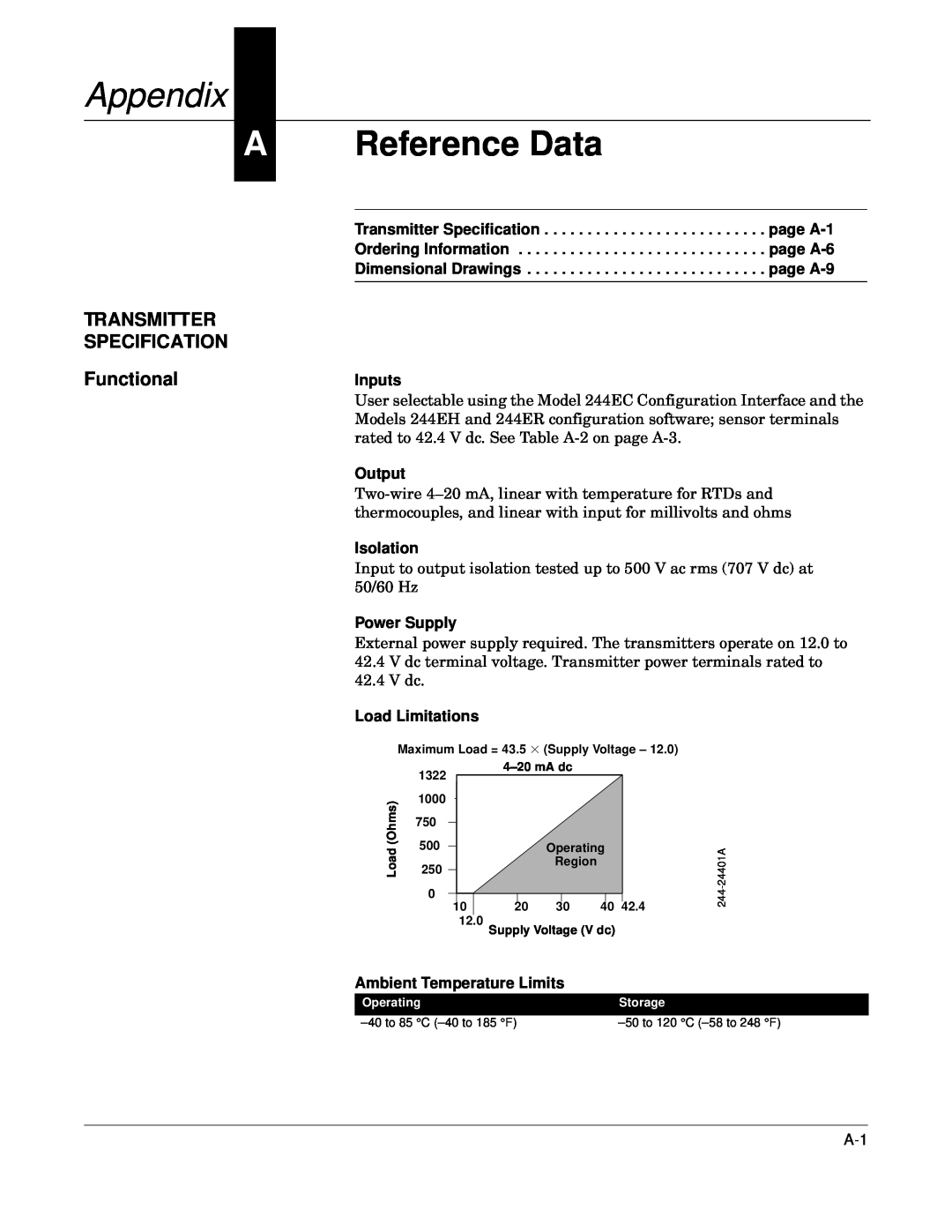
TRANSMITTER SPECIFICATION Functional
Appendix
A Reference Data
CE Electromagnetic Compatibility Compliance Testing
Performance
Update Time
Power Supply Effect
Input
Accuracy
TABLE A-2. Model 244E Input Options and Accuracy
Sensor
Ambient Temperature Effect
Transmitters can be installed in locations where the ambient
Materials of Construction
Physical
Weight
Electrical Connections
Head
ORDERING INFORMATION
Model
Product Description
Part Description
TABLE A-5. Model 244EC Configuration Interface Ordering Information
TABLE A-6. Transmitter Accessories
Typical Model Number 244EC
Tagging
Standard Configuration
Custom Configuration
Unless specified, transmitter will be shipped as follows
Model 244ER
DIMENSIONAL DRAWINGS Transmitter
Enclosure and Model 244EC Configuration Interface
Configuration Interface
Page
B Approvals
HAZARDOUS LOCATIONS INSTALLATIONS
LOCATIONS CERTIFICATIONS
Factory Mutual FM Approvals
Canadian Standards Association CSA Approvals
Standard Australia Quality Assurance Service SAA
KEMA Approvals
Special Conditions for Safe Use
Gostandart
INSTALLATION DRAWINGS
Installation Drawing Rev. AB
Figure B-1. Canadian Standards Association CSA Intrinsic Safety
Figure B-2. Canadian Standards Association CSA Explosion-Proof
Installation Drawing Rev. AA
00644-0009, Rev. AA
Figure B-3. Factory Mutual FM Intrinsic Safety Installation Drawing
00644-1049, Rev. AB
Figure B-4. Factory Mutual FM Explosion-Proof Installation Drawing
C Models 644 and 244E Temperature Transmitters Manual Supplement
Models 644H and 244EH
Transmitter Design Sensor Wiring Diagrams Special Mounting
OLD TRANSMITTER
Considerations
Use with an Existing DIN Plate Style Sensor
NEW TRANSMITTER
Considerations HART Communicator Model 644H only
2. Select 1 Off-line, 1 New Configuration, Rosemount, 644 Temp
Entity Parameters
SPECIFICATIONS
BASEFFA1 Intrinsically Safe Installation Entity Parameters
Factory Mutual3
Index
Wiring
Page
Product documentation available at