CABINET PREPARATION
1.To ensure professional results, the cabinet and countertop openings should be prepared by a qualified cabinet worker. We recommend having the cooktop available before cutting the opening for more precise dimension verification.
2.The clearances shown in Fig. 8 pg. 14 are required for all types of backguard installations.
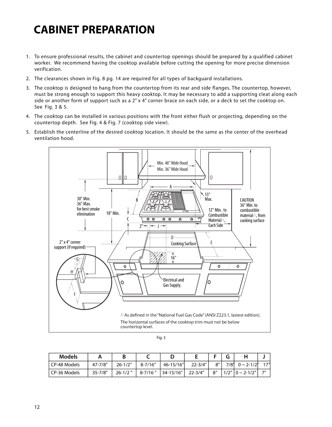
3.The cooktop is designed to hang from the countertop from its rear and side flanges. The countertop, however, must be strong enough to support this heavy cooktop. It may be necessary to add a supporting cleat along each side or another form of support such as a 2” x 4” corner brace on each side, or a deck to set the cooktop on.
See Fig. 3 & 5.
4.The cooktop can be installed in various positions with the front either flush or projecting, depending on the countertop depth. See Fig. 4 & Fig. 7 (cooktop side view).
5.Establish the centerline of the desired cooktop location. It should be the same as the center of the overhead ventilation hood.
Min. 48" Wide Hood
Min. 36" Wide Hood
|
| A |
30" Min. |
| 13" |
B | Max. | |
36" Max. |
|
|
for best smoke | 18" Min. | 12" Min. to |
elimination | Combustible |
C![]()
![]()
![]()
![]()
![]()
![]()
![]()
![]() Material#,
Material#,
2" | J |
| Each Side |
2" x 4" corner |
| D | E |
| Cooking Surface | ||
support (if required) |
|
|
|
G |
| 16" |
|
|
|
| |
H |
|
|
|
|
| Electrical and |
|
|
| Gas Supply. |
|
F |
|
|
|
CAUTION
36" Min. to combustible material#, from cooking surface
#As defined in the “National Fuel Gas Code” (ANSI Z223.1, lastest edition).
The horizontal surfaces of the cooktop trim must not be below countertop level.
Fig. 3
Models | A | B | C | D | E | F | G | H | J |
|
|
|
|
|
|
|
|
|
|
8” | 7/8” | 0 ~ | 17” | ||||||
|
|
|
|
|
|
|
|
|
|
8” | 1/2” | 0 ~ | 7” | ||||||
|
|
|
|
|
|
|
|
|
|
12