CONTROL PANEL INDEXING
The exhaust discharges vertically from outside the vent cover. The heater control panel assembly on top of the jacket can be turned to any of six positions for convenient access to the panel as follows:
1.Unbolt and separate the jacket halves.
2.Pull hair pin clips.
3.Depress plastic clips on the control panel assembly.
4.Lift panel off of support plate.
5.Turn the assembly to the desired position and snap in place.
6.Make sure that the operating controls can be adjusted without having to lean over the exhaust vent.
7.Replace hair pin clips.
8.Replace jacket halves and bolts and tighten.
5
4
![]() 3
3 ![]()
2
1
2732 1296
FIGURE 9: Indexing Control Panel
INDOOR INSTALLATION
INSTRUCTIONS
NOTICE: Local codes may restrict indoor installations. Consult local code officials.
![]()
![]()
![]()
![]()
![]()
![]()
![]()
![]()
![]() Risk of asphyxiation if exhaust is not correct- ly vented. Follow venting instructions exactly when installing heater. Do not use a draft hood with this heater,
Risk of asphyxiation if exhaust is not correct- ly vented. Follow venting instructions exactly when installing heater. Do not use a draft hood with this heater,
as the exhaust is under pressure from the burner blower and a draft hood will allow exhaust fumes to blow into the room housing the heater. Exhaust venting to the outdoors is required for all indoor installations.
![]()
![]()
![]()
![]()
![]()
![]()
![]()
![]()
![]() Risk of explosion if an LP (propane) gas unit is installed in a pit or other low spot. LP gas is heavier than air. Do not install the heater using LP gas in pits or other locations where gas might collect. Consult your local building code officials to determine installation require- ments of heater relative to LP gas storage tanks and filling equipment. Installation must meet the requirements for the Standard for the Storage and Handling of Liquified Petroleum Gases, ANSI/NFPA 58 (latest edition). Consult local codes and fire protection authorities about specific installation restrictions.
Risk of explosion if an LP (propane) gas unit is installed in a pit or other low spot. LP gas is heavier than air. Do not install the heater using LP gas in pits or other locations where gas might collect. Consult your local building code officials to determine installation require- ments of heater relative to LP gas storage tanks and filling equipment. Installation must meet the requirements for the Standard for the Storage and Handling of Liquified Petroleum Gases, ANSI/NFPA 58 (latest edition). Consult local codes and fire protection authorities about specific installation restrictions.
The heater is design certified by CSA International for installation on combustible flooring; in alcoves; in base- ments; in closets or utility rooms.
INSTALLATION IN A GARAGE
OR UTILITY ROOM
![]()
![]()
![]()
![]()
![]()
![]()
![]()
![]()
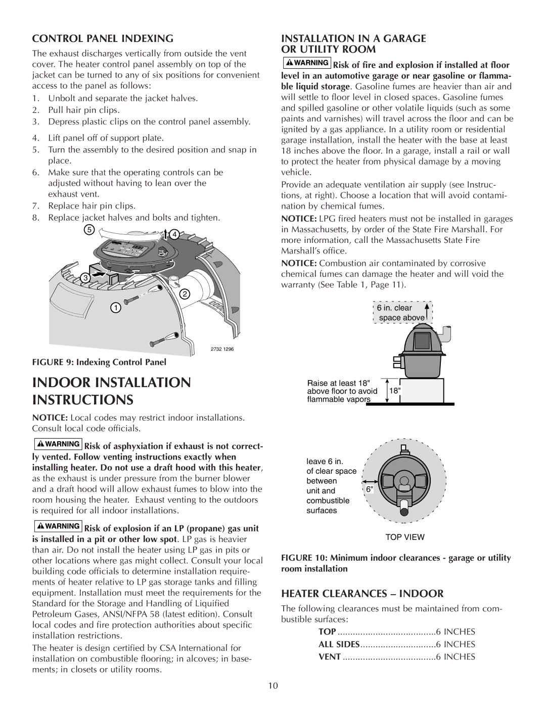
![]() Risk of fire and explosion if installed at floor level in an automotive garage or near gasoline or flamma- ble liquid storage. Gasoline fumes are heavier than air and will settle to floor level in closed spaces. Gasoline fumes and spilled gasoline or other volatile liquids (such as some paints and varnishes) will travel across the floor and can be ignited by a gas appliance. In a utility room or residential garage installation, install the heater with the base at least 18 inches above the floor. In a garage, install a rail or wall to protect the heater from physical damage by a moving vehicle.
Risk of fire and explosion if installed at floor level in an automotive garage or near gasoline or flamma- ble liquid storage. Gasoline fumes are heavier than air and will settle to floor level in closed spaces. Gasoline fumes and spilled gasoline or other volatile liquids (such as some paints and varnishes) will travel across the floor and can be ignited by a gas appliance. In a utility room or residential garage installation, install the heater with the base at least 18 inches above the floor. In a garage, install a rail or wall to protect the heater from physical damage by a moving vehicle.
Provide an adequate ventilation air supply (see Instruc- tions, at right). Choose a location that will avoid contami- nation by chemical fumes.
NOTICE: LPG fired heaters must not be installed in garages in Massachusetts, by order of the State Fire Marshall. For more information, call the Massachusetts State Fire Marshall’s office.
NOTICE: Combustion air contaminated by corrosive chemical fumes can damage the heater and will void the warranty (See Table 1, Page 11).
6 in. clear ![]() space above
space above
Raise at least 18" ![]()
![]() above floor to avoid 18" flammable vapors
above floor to avoid 18" flammable vapors
leave 6 in.
of clear space between
unit and | 6" |
|
combustible surfaces
TOP VIEW
FIGURE 10: Minimum indoor clearances - garage or utility room installation
HEATER CLEARANCES – INDOOR
The following clearances must be maintained from com- bustible surfaces:
TOP | 6 INCHES |
ALL SIDES | 6 INCHES |
VENT | 6 INCHES |
10