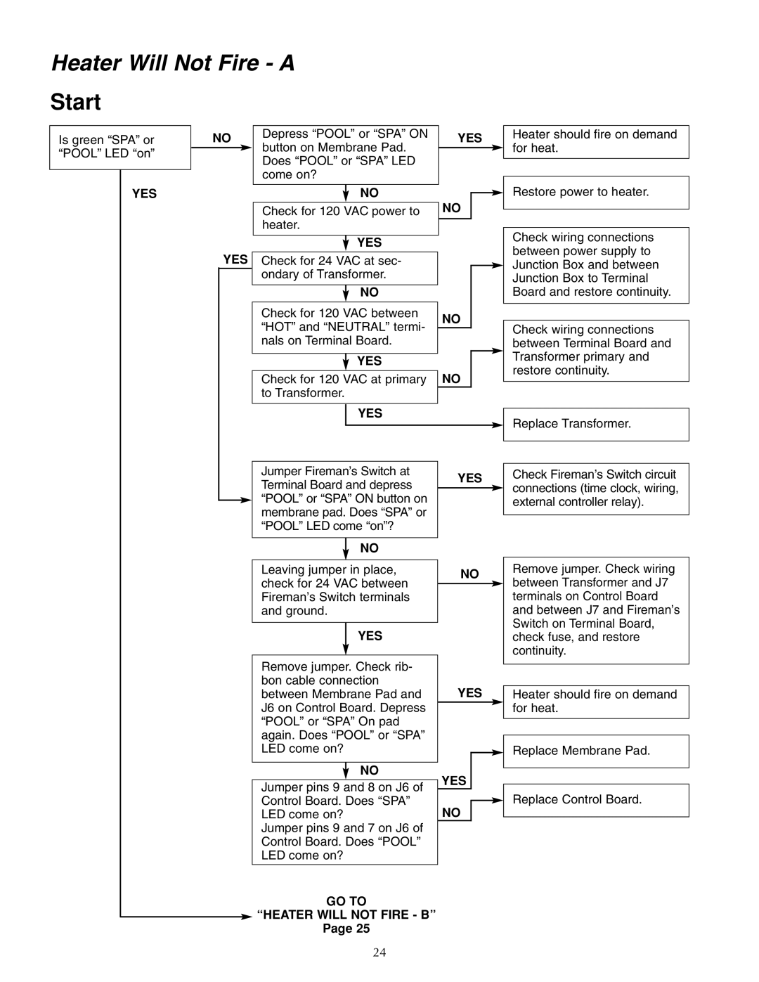
Heater Will Not Fire - A
Start
Is green “SPA” or | NO |
| Depress “POOL” or “SPA” ON | YES |
| button on Membrane Pad. | |||
“POOL” LED “on” |
|
|
| |
|
| Does “POOL” or “SPA” LED |
| |
|
|
|
| |
|
|
| come on? |
|
|
|
| ||
|
|
|
|
|
Heater should fire on demand for heat.
YES
YES
NO
Check for 120 VAC power to heater.
YES
Check for 24 VAC at sec- ondary of Transformer.
NO
Check for 120 VAC between “HOT” and “NEUTRAL” termi- nals on Terminal Board.
YES
Check for 120 VAC at primary to Transformer.
YES
NO
NO
NO
Restore power to heater.
Check wiring connections between power supply to Junction Box and between Junction Box to Terminal Board and restore continuity.
Check wiring connections between Terminal Board and Transformer primary and restore continuity.
Replace Transformer.
Jumper Fireman’s Switch at | YES | |
Terminal Board and depress | ||
| ||
| ||
“POOL” or “SPA” ON button on |
| |
membrane pad. Does “SPA” or |
| |
“POOL” LED come “on”? |
| |
|
|
| NO |
|
| |
|
|
| ||
Leaving jumper in place, | NO | |||
check for 24 VAC between | ||||
|
| |||
|
| |||
Fireman’s Switch terminals |
|
| ||
and ground. |
|
| ||
|
|
|
| |
| YES |
|
| |
|
|
| ||
Remove jumper. Check rib- |
|
| ||
bon cable connection | YES | |||
between Membrane Pad and | ||||
J6 on Control Board. Depress |
|
| ||
“POOL” or “SPA” On pad |
|
| ||
again. Does “POOL” or “SPA” |
|
| ||
LED come on? |
|
| ||
|
|
|
| |
| NO | YES |
| |
|
| |||
|
|
| ||
Jumper pins 9 and 8 on J6 of | ||||
|
| |||
Control Board. Does “SPA” | NO |
| ||
| ||||
LED come on? |
| |||
Jumper pins 9 and 7 on J6 of |
|
| ||
Control Board. Does “POOL” |
|
| ||
LED come on? |
|
| ||
|
|
|
| |
GO TO
“HEATER WILL NOT FIRE - B”
Page 25
Check Fireman’s Switch circuit connections (time clock, wiring, external controller relay).
Remove jumper. Check wiring between Transformer and J7 terminals on Control Board and between J7 and Fireman’s Switch on Terminal Board, check fuse, and restore continuity.
Heater should fire on demand for heat.
Replace Membrane Pad.
Replace Control Board.
24
