Pool Heater Wiring Connection Diagram
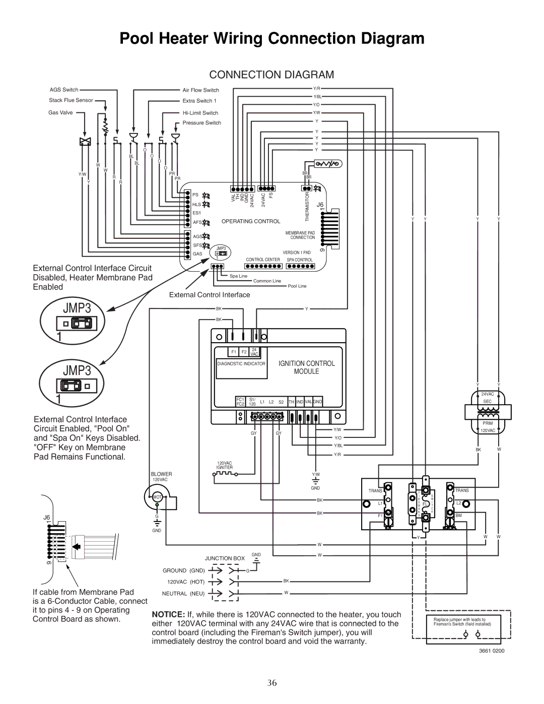
CONNECTION DIAGRAM
AGS Switch
Stack Flue Sensor
Gas Valve
O |
BL O
WBL
W
Y/W
R
YR
External Control Interface Circuit
Disabled, Heater Membrane Pad
Enabled
JMP3
1
JMP3
1
External Control Interface Circuit Enabled, "Pool On" and "Spa On" Keys Disabled. "OFF" Key on Membrane Pad Remains Functional.
Air Flow Switch |
|
| Y/R |
|
|
|
| ||
|
| Y/BL | ||
|
|
| ||
|
|
| ||
Extra Switch 1
|
|
|
|
|
|
|
|
| Y/O |
|
|
|
|
|
|
|
| Y/W | |||
Pressure Switch |
|
|
|
|
|
|
| Y |
| |
|
|
|
|
|
|
|
|
| Y |
|
|
|
|
|
|
|
|
|
| Y |
|
|
|
|
|
|
|
|
|
| Y |
|
|
|
|
|
|
|
|
|
| Y |
|
O |
|
|
|
|
|
|
|
|
|
|
O |
|
|
|
|
|
|
|
|
|
|
PR |
|
|
|
|
|
|
| BR |
|
|
PR |
|
|
|
|
|
|
| BR |
|
|
|
|
|
|
|
|
|
|
|
| |
PS | VAL TH IND | GND | 24VAC | 24VAC | FS |
| THERMISTOR |
|
| |
HLS |
| J6 | ||||||||
ES1 |
|
| 1 | |||||||
AFS |
|
| ||||||||
OPERATING CONTROL |
|
|
| |||||||
AGS |
|
|
|
|
|
|
| MEMBRANE PAD |
| |
|
|
|
|
|
|
| CONNECTION |
| ||
SFS | JMP3 |
|
|
|
|
|
|
|
| 9 |
|
|
|
|
|
| VERSION 1 PAD |
| |||
GAS |
|
|
|
|
|
|
| |||
|
|
|
|
|
|
|
| |||
1 |
|
|
|
|
|
|
|
|
| |
|
| CONTROL CENTER | SPA CONTROL |
|
| |||||
|
|
|
|
| ||||||
| Spa Line | Common Line |
|
|
| |||||
|
|
|
|
|
|
| ||||
|
|
|
|
|
|
|
| Pool Line |
|
|
External Control Interface |
|
|
|
|
|
|
| |||
| BK |
|
|
|
|
|
| Y |
|
|
| BK |
|
|
|
|
|
|
|
|
|
| F1 | F2 | 24 |
|
|
|
|
|
| |
| VAC |
|
|
|
|
|
| |||
|
|
|
|
|
|
|
|
|
| |
| DIAGNOSTIC INDICATOR |
| IGNITION CONTROL | |||||||
|
|
|
|
|
|
|
| MODULE |
| |
|
| FC1 | S1/ | L1 | L2 | S2 | TH IND VAL GND | |||
|
| FC2 | 120 | |||||||
|
|
|
|
|
|
|
| |||
|
|
|
| GY |
|
| GY |
|
| Y/W |
|
|
|
|
|
|
|
| Y/O | ||
|
|
|
|
|
|
|
|
|
| |
|
|
|
|
|
|
|
|
|
| Y/BL |
|
|
|
|
|
|
|
|
|
| Y/R |
| 120VAC |
|
|
|
|
|
|
|
|
|
| IGNITER |
|
|
|
|
|
|
|
|
|
Y YYY
YY
24VAC
SEC
PRIM ![]() 120VAC
120VAC ![]()
BK W
BLOWER | Y/W |
120VAC
|
| GND | TRANS |
| |
|
|
| F | ||
| MOT |
|
| I | |
|
| BK |
| R | |
|
| L1 | ME FL | ||
|
|
| |||
|
|
|
| A | |
|
| BK | F1 | N | |
J6 | G | S | |||
| |||||
|
| ||||
1 |
|
|
|
|
GND |
|
| Y |
| W |
GND | W |
JUNCTION BOX |
|
9
GROUND (GND) | G |
120VAC (HOT) | BK |
S
W
I
T
C H
TRANS
L2
BM
W W
If cable from Membrane Pad
is a
NEUTRAL (NEU) | W |
NOTICE: If, while there is 120VAC connected to the heater, you touch either 120VAC terminal with any 24VAC wire that is connected to the control board (including the Fireman's Switch jumper), you will immediately destroy the control board and void the warranty.
Replace jumper with leads to Fireman's Switch (field installed)
3661 0200
36