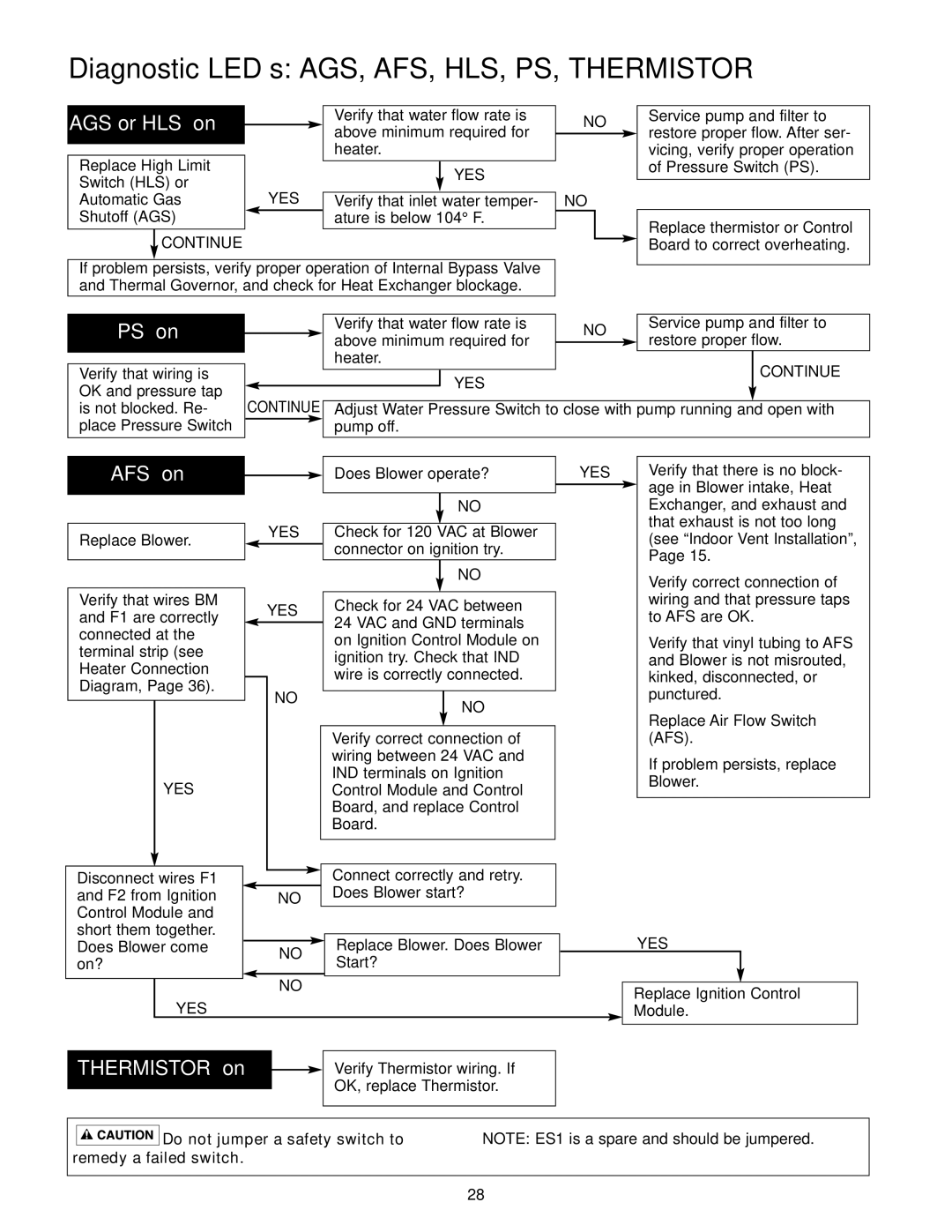
Diagnostic LED’s: AGS, AFS, HLS, PS, THERMISTOR
AGS or HLS “on” 
Replace High Limit |
|
| |
Switch (HLS) or |
| YES | |
Automatic Gas |
| ||
Shutoff (AGS) |
|
| |
|
| ||
|
|
|
|
| CONTINUE |
|
|
|
|
| |
Verify that water flow rate is above minimum required for heater.
YES
Verify that inlet water temper- ature is below 104° F.
NO
NO
Service pump and filter to restore proper flow. After ser- vicing, verify proper operation of Pressure Switch (PS).
Replace thermistor or Control Board to correct overheating.
If problem persists, verify proper operation of Internal Bypass Valve and Thermal Governor, and check for Heat Exchanger blockage.
PS “on”
Verify that wiring is OK and pressure tap is not blocked. Re- place Pressure Switch
|
|
| Verify that water flow rate is | NO | Service pump and filter to | |||
|
|
| above minimum required for | restore proper flow. | ||||
|
|
|
|
| ||||
|
|
| ||||||
|
|
| heater. |
|
|
| CONTINUE | |
|
|
|
| YES |
|
|
| |
|
|
|
|
|
|
|
| |
|
|
|
|
|
|
|
| |
|
|
|
|
|
|
|
|
|
CONTINUE Adjust Water Pressure Switch to close with pump running and open with pump off.
AFS “on”
Replace Blower.
Verify that wires BM and F1 are correctly connected at the terminal strip (see Heater Connection Diagram, Page 36).
YES
Disconnect wires F1 and F2 from Ignition Control Module and short them together. Does Blower come on?
Does Blower operate?
NO
YES Check for 120 VAC at Blower ![]() connector on ignition try.
connector on ignition try.
|
|
|
|
| NO |
|
|
|
|
|
|
| YES | Check for 24 VAC between | |||
|
|
| 24 VAC and GND terminals | ||
|
|
| |||
|
|
| on Ignition Control Module on | ||
|
|
| ignition try. Check that IND | ||
|
| NO | wire is correctly connected. | ||
|
| ||||
|
|
|
|
| |
|
|
|
| NO | |
|
|
|
| ||
|
|
|
|
| |
Verify correct connection of wiring between 24 VAC and IND terminals on Ignition Control Module and Control Board, and replace Control Board.
| Connect correctly and retry. |
NO | Does Blower start? |
|
NO | Replace Blower. Does Blower | |
Start? | ||
|
YES | Verify that there is no block- | |
|
| age in Blower intake, Heat |
|
| |
|
| Exchanger, and exhaust and |
|
| that exhaust is not too long |
|
| (see “Indoor Vent Installation”, |
|
| Page 15. |
|
| Verify correct connection of |
|
| wiring and that pressure taps |
|
| to AFS are OK. |
|
| Verify that vinyl tubing to AFS |
|
| and Blower is not misrouted, |
|
| kinked, disconnected, or |
|
| punctured. |
|
| Replace Air Flow Switch |
|
| (AFS). |
|
| If problem persists, replace |
|
| Blower. |
|
|
|
YES
NO
YES
THERMISTOR “on” |
|
| Verify Thermistor wiring. If |
| |||
|
|
| OK, replace Thermistor. |
|
| ||
|
|
|
|
Replace Ignition Control Module.


 Do not jumper a safety switch to remedy a failed switch.
NOTE: ES1 is a spare and should be jumpered.
28
