Manuals
/
Fluke
/
Household Appliance
/
Sewing Machine
Fluke
fluke123
user manual
ScopeMeter Test Tool Kit
Models:
fluke123
1
10
77
77
Download
77 pages
58.02 Kb
7
8
9
10
11
12
13
14
Specs
Performance Characteristics
Measuring Video Signals
Setting the Power Down Timer
Connecting a Computer
Resetting the Test Tool
Parts and Accessories
Measurement Setup
Charging the Battery Pack
Adjusting Scope Probes
Page 10
Image 10
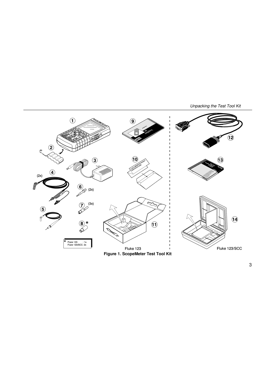
Unpacking the Test Tool Kit
Figure 1. ScopeMeter Test Tool Kit
3
Page 9
Page 11
Page 10
Image 10
Page 9
Page 11
Contents
Fluke
Limited Warranty & Limitation of Liability
Service Centers
Table of Contents
Fluke
Iii
Specifications
Statement of Conformity
Declaration of Conformity
Manufacturer
Sample tests
Model
Unpacking the Test Tool Kit
# Description
123 123/SCC
ScopeMeter Test Tool Kit
Safely Using the Test Tool
Safely Using the Test Tool
Fluke
Powering the Test Tool
Goal of this Chapter
Resetting the Test Tool
Screen After Reset
Changing Backlight
Reading the Screen
From full to empty
Making Selections in a Menu
Basic Navigation
Input a
Looking at the Measurement Connections
Input B
Displaying an Unknown Signal with Connect-and View
Screen After an Auto Set
Measurement Setup
Making Measurements
Hz and Vpp as Main Readings
Holding a Stable Reading
Freezing the Screen
Touch Hold OFF appears on
Making Relative Measurements
Making a Relative Measurement
Changing the Time Base
Selecting Auto/Manual Ranges
Changing the Graphic Representation on the Screen
Changing the Amplitude
Observe that the trigger identifier moves horizontally
Positioning the Waveform on the Screen
On the screen
Smoothing the Waveform
11. Smoothing the Waveform
Displaying the Envelope of a Waveform
12. Displaying the Envelope of a Waveform
TrendPlotting a Waveform
Starting a TrendPlot function
Turning Off the TrendPlot Display
Acquiring the Waveform
Changing the TrendPlot Reading
Making a Single Acquisition
14. Making a Single Acquisition
Recording Slow Signals over a Long Period of Time
Start Recording
Selecting AC-Coupling
Reversing the Polarity of the Displayed Waveform
Setting Trigger Level and Slope
Triggering on a Waveform
Selecting the Trigger Parameters
Isolated Triggering Triggering on Video Signals
17. Isolated Triggering
18. Measuring Video Signals
Triggering on a Specific Video Line
Saving Screens
Saving and Recalling a Setup or a Screen
Recalling Screens
Deleting Screens
Using a Printer
19. Connecting a Serial Printer
Using FlukeView Software
21. Connecting a Computer
About this Chapter
Cleaning the Test Tool
Storing the Test Tool
Charging the Ni-Cd Battery Pack
Charging the Battery Pack
Keeping Batteries in Optimal Condition
Replacing and Disposing of the Ni-Cd Battery Pack
Replacing the Battery Pack
Using and Adjusting 101 Scope Probes
Adjusting Scope Probes
Standard Accessories
Parts and Accessories
Calibrating the Test Tool
Standard Accessories
Ordering Code
Maintaining the Test Tool Parts and Accessories
Optional Accessories
SW90W
Using the Tilt Stand
Using the Tilt Stand
Changing the Information Language
Setting the Grid Display Adjusting the Screen Contrast
Changing the Display
Changing Date and Time
Saving Battery Life
Setting the Power Down Timer
Changing the Auto Set Options
Using Proper Grounding
Potential
Battery Testing of Fluke Accessories
Solving Printing and Other Communication Errors
Fluke multimeter
Introduction
Performance Characteristics
Safety Characteristics
Environmental Data
Dual Input Oscilloscope
Vertical
Ranges
Horizontal
Trigger
Sampling Rate for both channels simultaneously
Display Modes
Advanced Scope Functions
Auto Set
Dual Input Meter
Input a and Input B
Pulse Width Pulse
Phase
Duty Cycle Duty
Decibel dB
Advanced Meter Functions
Display
Power
Miscellaneous
Memory
Environmental
Electromagnetic Compatibility EMC
Max. Input Voltage Input a and B
Safety
Up to 400 Hz
= 10 V/m
Trace disturbance with STL120 No visible disturbance
= 3 V/m
Disturbance less than 10% of full scale
VDC, VAC, VAC+DC OHM, CONT, Diode CAP
Index
Fluke
Index
Fluke
Top
Page
Image
Contents