Using The Test Tool | 1 |
Triggering on a Waveform |
Isolated Triggering | Triggering on Video Signals |
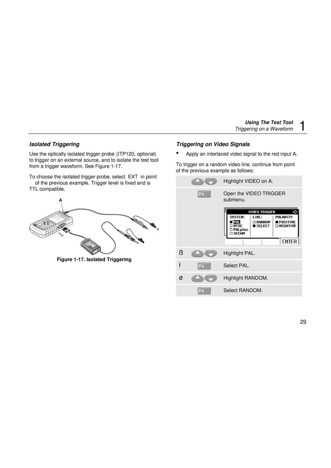
Use the optically isolated trigger probe (ITP120, optional) to trigger on an external source, and to isolate the test tool from a trigger waveform. See Figure
∙Apply an interlaced video signal to the red input A.
To trigger on a random video line, continue from point of the previous example as follows:
To choose the isolated trigger probe, select ‘EXT’ in point
of the previous example. Trigger level is fixed and is TTL compatible.
Figure 1-17. Isolated Triggering
![]()
![]()
![]()


Highlight VIDEO on A.
Open the VIDEO TRIGGER submenu.
Highlight PAL.
Select PAL.
Highlight RANDOM.
Select RANDOM.
29