Connecting a
This section describes:
•Connecting a
•Connecting the
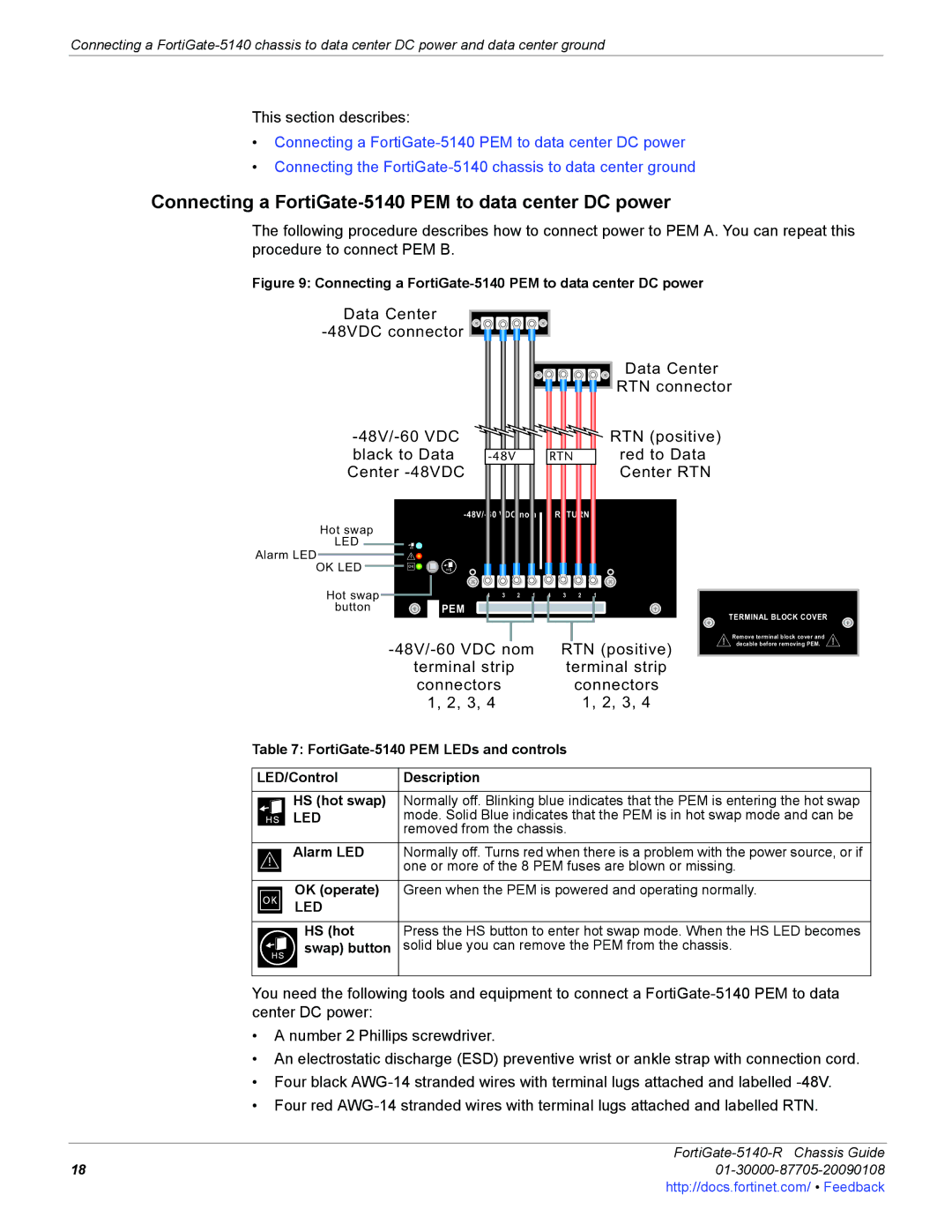
Connecting a FortiGate-5140 PEM to data center DC power
The following procedure describes how to connect power to PEM A. You can repeat this procedure to connect PEM B.
Figure 9: Connecting a FortiGate-5140 PEM to data center DC power
Data Center ![]()
Data Center
RTN connector
|
|
|
|
|
|
| RTN (positive) | ||
black to Data |
|
| RTN |
| red to Data | ||||
Center |
|
|
|
|
|
|
| Center RTN | |
|
| RETURN |
| ||||||
Hot swap |
| 4 | 3 | 2 | 1 | 4 | 3 | 2 | 1 |
|
|
|
|
|
|
|
|
| |
LED |
|
|
|
|
|
|
|
|
|
Alarm LED |
|
|
|
|
|
|
|
|
|
OK LED |
|
|
|
|
|
|
|
|
|
Hot swap |
| 4 | 3 | 2 | 1 | 4 | 3 | 2 | 1 |
button | PEM |
|
|
|
|
|
|
|
|
TERMINAL BLOCK COVER
|
|
|
|
|
|
|
| Remove terminal block cover and | |
|
| RTN (positive) | decable before removing PEM. | ||||||
|
|
| |||||||
| terminal strip |
| terminal strip |
|
| ||||
| connectors |
|
| connectors |
|
| |||
| 1, 2, 3, 4 |
| 1, 2, 3, 4 |
|
| ||||
Table 7: |
|
| |||||||
|
|
|
|
|
|
|
|
|
|
LED/Control | Description |
|
|
|
|
|
| ||
|
|
|
|
|
|
|
| ||
HS (hot swap) | Normally off. Blinking blue indicates that the PEM is entering the hot swap | ||||||||
LED | mode. Solid Blue indicates that the PEM is in hot swap mode and can be | ||||||||
| removed from the chassis. |
|
| ||||||
Alarm LED | Normally off. Turns red when there is a problem with the power source, or if | ||||||||
| one or more of the 8 PEM fuses are blown or missing. | ||||||||
|
|
|
|
|
|
|
| ||
OK (operate) | Green when the PEM is powered and operating normally. | ||||||||
LED |
|
|
|
|
|
|
|
|
|
|
|
|
|
|
|
|
| ||
HS (hot | Press the HS button to enter hot swap mode. When the HS LED becomes | ||||||||
swap) button | solid blue you can remove the PEM from the chassis. | ||||||||
|
|
|
|
|
|
|
|
|
|
You need the following tools and equipment to connect a
•A number 2 Phillips screwdriver.
•An electrostatic discharge (ESD) preventive wrist or ankle strap with connection cord.
•Four black
•Four red
FortiGate-5140-R Chassis Guide
1801-30000-87705-20090108http://docs.fortinet.com/ • Feedback