FortiGate-5140 chassis front panel
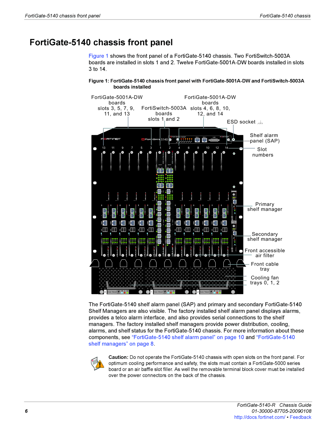
Figure 1 shows the front panel of a FortiGate-5140 chassis. Two FortiSwitch-5003A boards are installed in slots 1 and 2. Twelve FortiGate-5001A-DW boards installed in slots 3 to 14.
Figure 1: FortiGate-5140 chassis front panel with FortiGate-5001A-DW and FortiSwitch-5003A boards installed
|
|
|
|
|
| |||||||
| boards |
|
|
|
|
|
|
| boards | |||
slots 3, 5, 7, 9, | slots 4, 6, 8, 10, | |||||||||||
| 11, and 13 |
| boards | 12, and 14 | ||||||||
|
|
| slots 1 |
| and 2 |
| ESD socket | |||||
|
|
|
|
| ||||||||
|
|
|
|
|
|
|
|
|
|
| ||
|
|
|
|
|
|
|
|
|
|
|
|
|
| 5140SAP | SERIAL 1 | SERIAL 2 | ALARM |
5140 | CRITICALMAJORMINOR USER1 USER2 USER3 |
|
|
|
RESET |
|
|
|
Shelf alarm ![]()
![]() panel (SAP)
panel (SAP)
13 | 11 | 9 | 7 | 5 | 3 | 1 | 2 | 4 | 6 | 8 | 10 | 12 | 14 | Slot |
|
|
|
|
|
|
|
|
|
|
|
|
|
|
numbers
ETH0 ETH1 | 5000SM |
10/100 link/Act 10/100 link/Act |
ETH0
Service
RESET
STATUS
Hot Swap
1![]() 2
2![]()
Primary
shelf manager
ETH0 ETH1 |
10/100 link/Act 10/100 link/Act |
5000SM
|
| Service | Secondary |
|
| ETH0 | shelf manager |
|
| STATUS | |
|
| RESET |
|
|
| Hot Swap |
|
|
|
| Front accessible |
| FILTER |
| air filter |
|
|
| Front cable |
|
|
| tray |
|
|
| Cooling fan |
|
|
| trays 0, 1, 2 |
0 FAN TRAY | 1 FAN TRAY | 2 FAN TRAY |
|
The
Caution: Do not operate the
FortiGate-5140-R Chassis Guide
601-30000-87705-20090108http://docs.fortinet.com/ • Feedback