Schematic Diagram
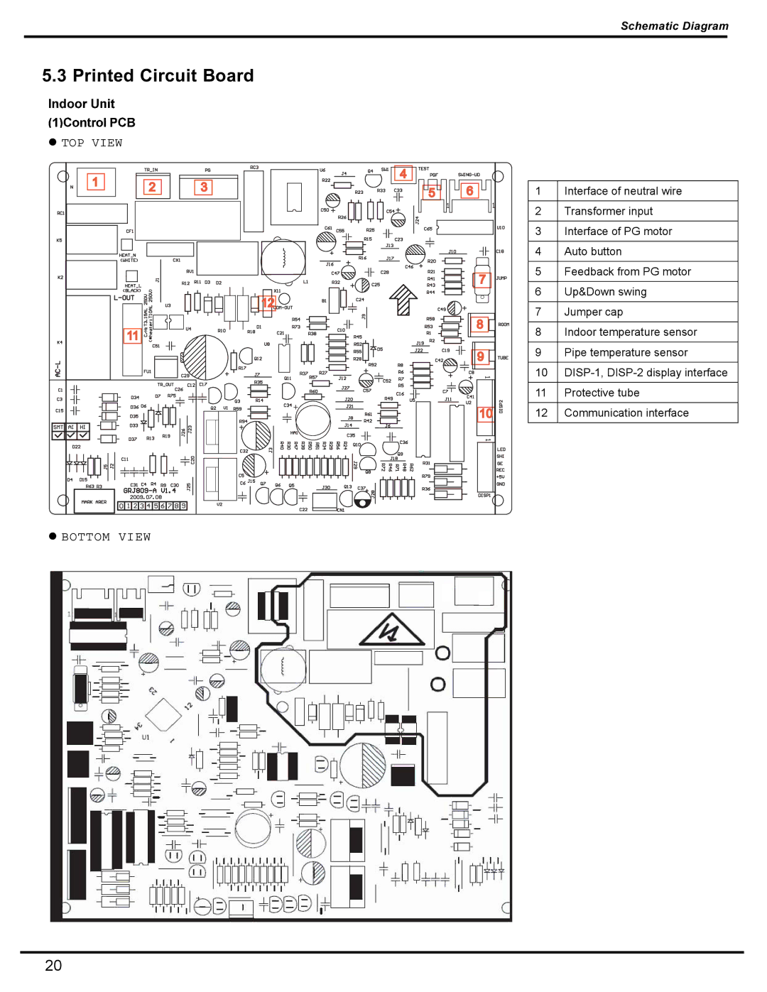
5.3 PRINTED CIRCUIT BOARD
 TOP VIEW
1 | 2 | 3 |
|
![]()
![]()
![]() 12
12![]()
![]()
![]()
11
 BOTTOM VIEW
4 |
|
5 | 6 |
| 7 |
| 8 |
| 9 |
| 10 |
1 | Interface of neutral wire |
|
|
2 | Transformer input |
|
|
3 | Interface of PG motor |
|
|
4 | Auto button |
|
|
5 | Feedback from PG motor |
|
|
6 | Up&Down swing |
|
|
7 | Jumper cap |
|
|
8 | Indoor temperature sensor |
|
|
9 | Pipe temperature sensor |
|
|
10 | |
|
|
11 | Protective tube |
|
|
12 | Communication interface |
|
|
20
