24G SERIES FLATBOTTOM GAS FRYERS CHAPTER 1: SERVICE PROCEDURES
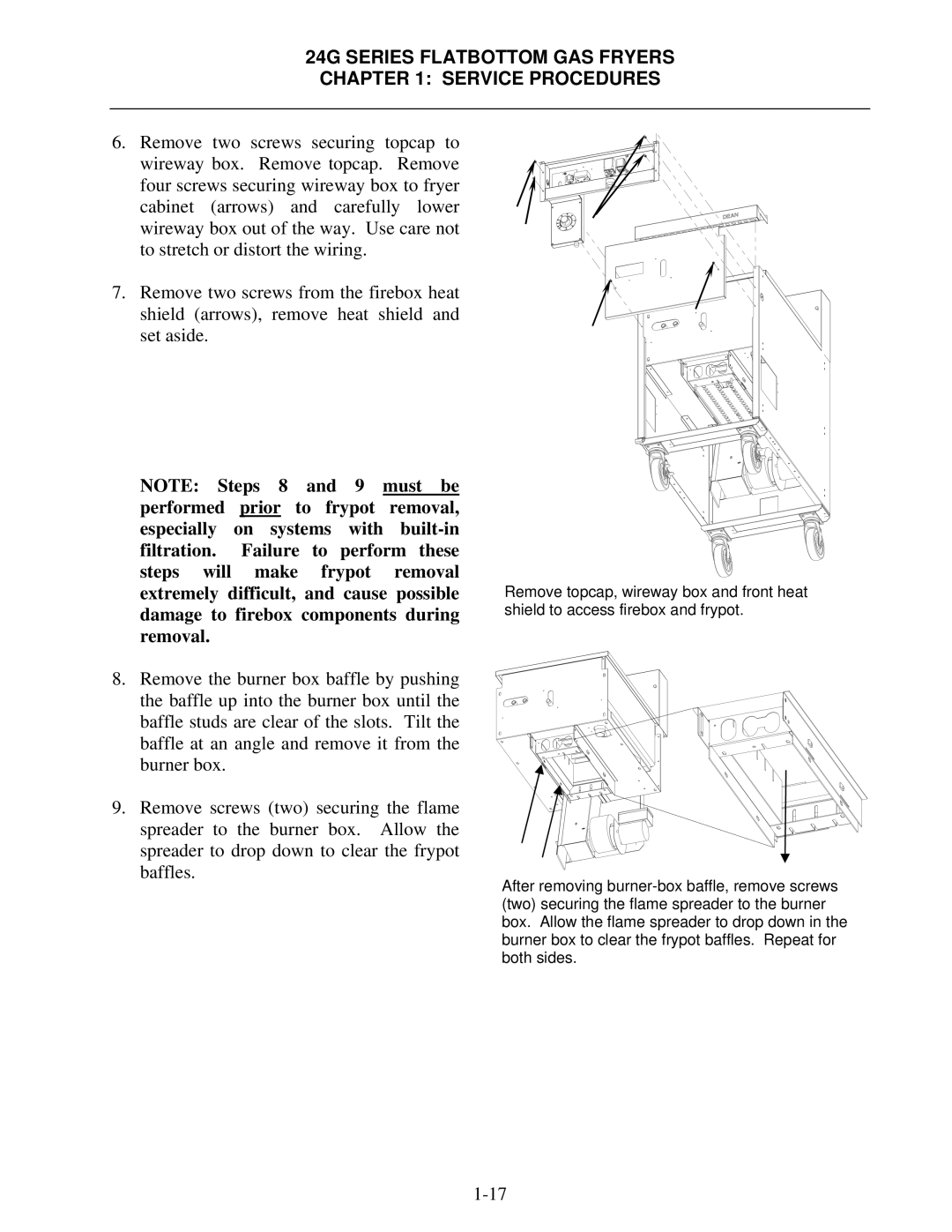
6.Remove two screws securing topcap to wireway box. Remove topcap. Remove four screws securing wireway box to fryer cabinet (arrows) and carefully lower wireway box out of the way. Use care not to stretch or distort the wiring.
7.Remove two screws from the firebox heat shield (arrows), remove heat shield and set aside.
NOTE: Steps 8 and 9 must be performed prior to frypot removal, especially on systems with
8.Remove the burner box baffle by pushing the baffle up into the burner box until the baffle studs are clear of the slots. Tilt the baffle at an angle and remove it from the burner box.
9.Remove screws (two) securing the flame spreader to the burner box. Allow the spreader to drop down to clear the frypot baffles.
Remove topcap, wireway box and front heat shield to access firebox and frypot.
After removing
