24G SERIES FLATBOTTOM GAS FRYERS CHAPTER 1: SERVICE PROCEDURES
1.10 WIRING DIAGRAMS
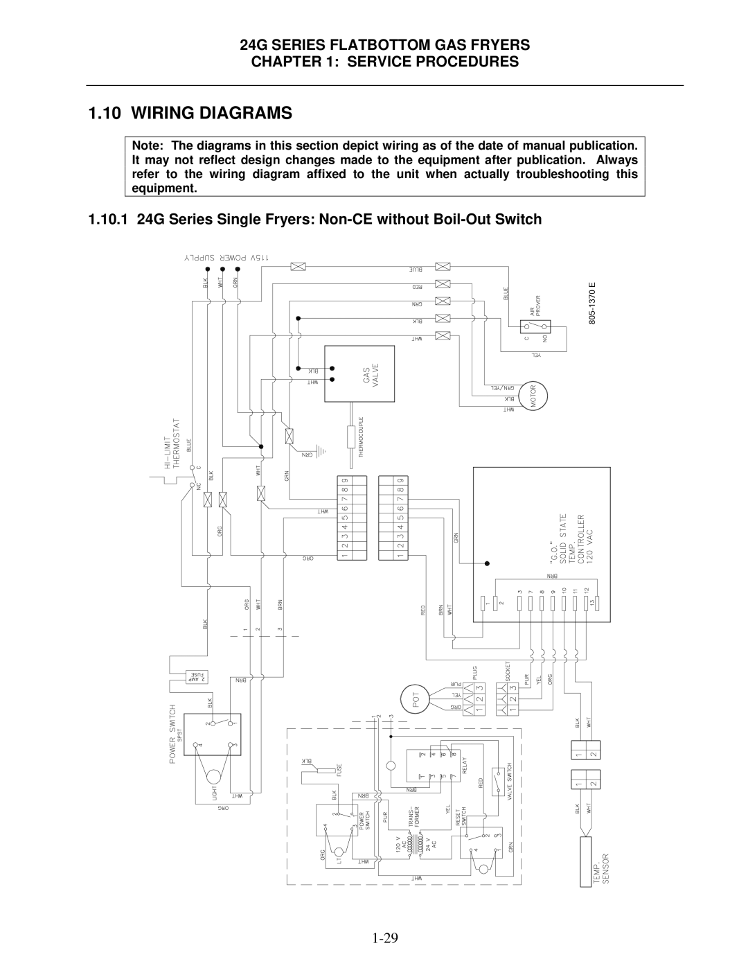
Note: The diagrams in this section depict wiring as of the date of manual publication. It may not reflect design changes made to the equipment after publication. Always refer to the wiring diagram affixed to the unit when actually troubleshooting this equipment.
1.10.1 24G Series Single Fryers: