TB14 SERIES GAS FRYERS
CHAPTER 9: PARTS LIST
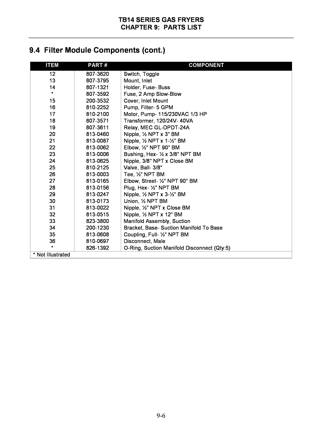
9.4 Filter Module Components (cont.)
ITEM | PART # | COMPONENT |
12 | 807-3620 | Switch, Toggle |
13 | 807-3795 | Mount, Inlet |
14 | 807-1321 | Holder, Fuse- Buss |
*807-3592 Fuse, 2 Amp Slow-Blow
15200-3532 Cover, Inlet Mount
16810-2252 Pump, Filter- 5 GPM
17810-2100 Motor, Pump- 115/230VAC 1/3 HP
18807-3571 Transformer, 120/24V- 40VA
19807-3611 Relay, MEC GL-DPDT-24A
20813-0460 Nipple, ½ NPT x 3" BM
21813-0087 Nipple, ½ NPT x 1-½" BM
22813-0062 Elbow, ½" NPT 90° BM
23813-0006 Bushing, Hex- ½ x 3/8" NPT BM
24813-0625 Nipple, 3/8" NPT x Close BM
25810-2125 Valve, Ball- 3/8"
26813-0003 Tee, ½" NPT BM
27813-0165 Elbow, Street- ½" NPT 90° BM
28813-0156 Plug, Hex- ½" NPT BM
29813-0247 Nipple, ½ NPT x 3-½" BM
30813-0173 Union, ½ NPT BM
31813-0022 Nipple, ½" NPT x Close BM
32813-0515 Nipple, ½ NPT x 12" BM
33823-3800 Manifold Assembly, Suction
34200-1230 Bracket, Base- Suction Manifold To Base
35813-0608 Coupling, Full- ½" NPT BM
36810-0697 Disconnect, Male
*826-1392 O-Ring, Suction Manifold Disconnect (Qty:5)
*Not Illustrated