Chapter 4 Connectors
4 Connectors
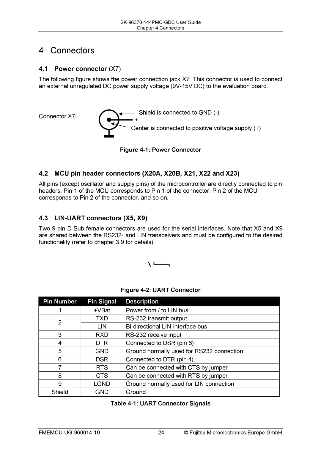
4.1Power connector (X7)
The following figure shows the power connection jack X7. This connector is used to connect an external unregulated DC power supply voltage
Connector X7: |
|
| + | Shield is connected to GND | ||
|
|
| ||||
|
|
|
|
|
| |
|
|
|
| Center is connected to positive voltage supply (+) | ||
|
|
| ||||
|
|
|
| Figure | ||
|
|
|
| |||
|
|
|
| |||
4.2MCU pin header connectors (X20A, X20B, X21, X22 and X23)
All pins (except oscillator and supply pins) of the microcontroller are directly connected to pin headers. Pin 1 of the MCU corresponds to Pin 1 of the connector. Pin 2 of the MCU corresponds to Pin 2 of the connector, and so on.
4.3LIN-UART connectors (X5, X9)
Two
|
| Figure | |
|
|
|
|
Pin Number | Pin Signal |
| Description |
1 | +VBat |
| Power from / to LIN bus |
2 | TXD |
| |
LIN |
| ||
|
| ||
3 | RXD |
| |
4 | DTR |
| Connected to DSR (pin 6) |
5 | GND |
| Ground normally used for RS232 connection |
6 | DSR |
| Connected to DTR (pin 4) |
7 | RTS |
| Can be connected with CTS by jumper |
8 | CTS |
| Can be connected with RTS by jumper |
9 | LGND |
| Ground normally used for LIN connection |
Shield | GND |
| Ground |
Table 4-1: UART Connector Signals
- 24 - | © Fujitsu Microelectronics Europe GmbH |