CONNECTING THE DISPLAY TO EXTERNAL EQUIPMENT
Be sure to turn OFF the power to the display and external equipment before making any connections.
No cables are supplied with the display for connection to external equipment. The type of cable to be used varies depending on the PC model. Contact your dealer for more information.
RECEPTACLE
Make sure that the power cable’s grounding wire is grounded.
The display comes with a
CONNECTING THE DISPLAY TO EXTERNAL EQUIPMENT
Carefully check the terminals for position and type before making any connections.
Loose connectors can result in image or color problems. Make sure that all connectors are securely inserted into their terminals.
Replace the connector cover onto the display when you finish making the connections.
Terminal | Connector |
|
|
VIDEO INPUT | BNC |
|
|
S terminal | |
|
|
COMPONENT VIDEO INPUT | BNC x 3 |
|
|
RGB INPUT | |
| BNC x 5 |
|
|
AUDIO INPUT | Pin jack |
|
|
|
|
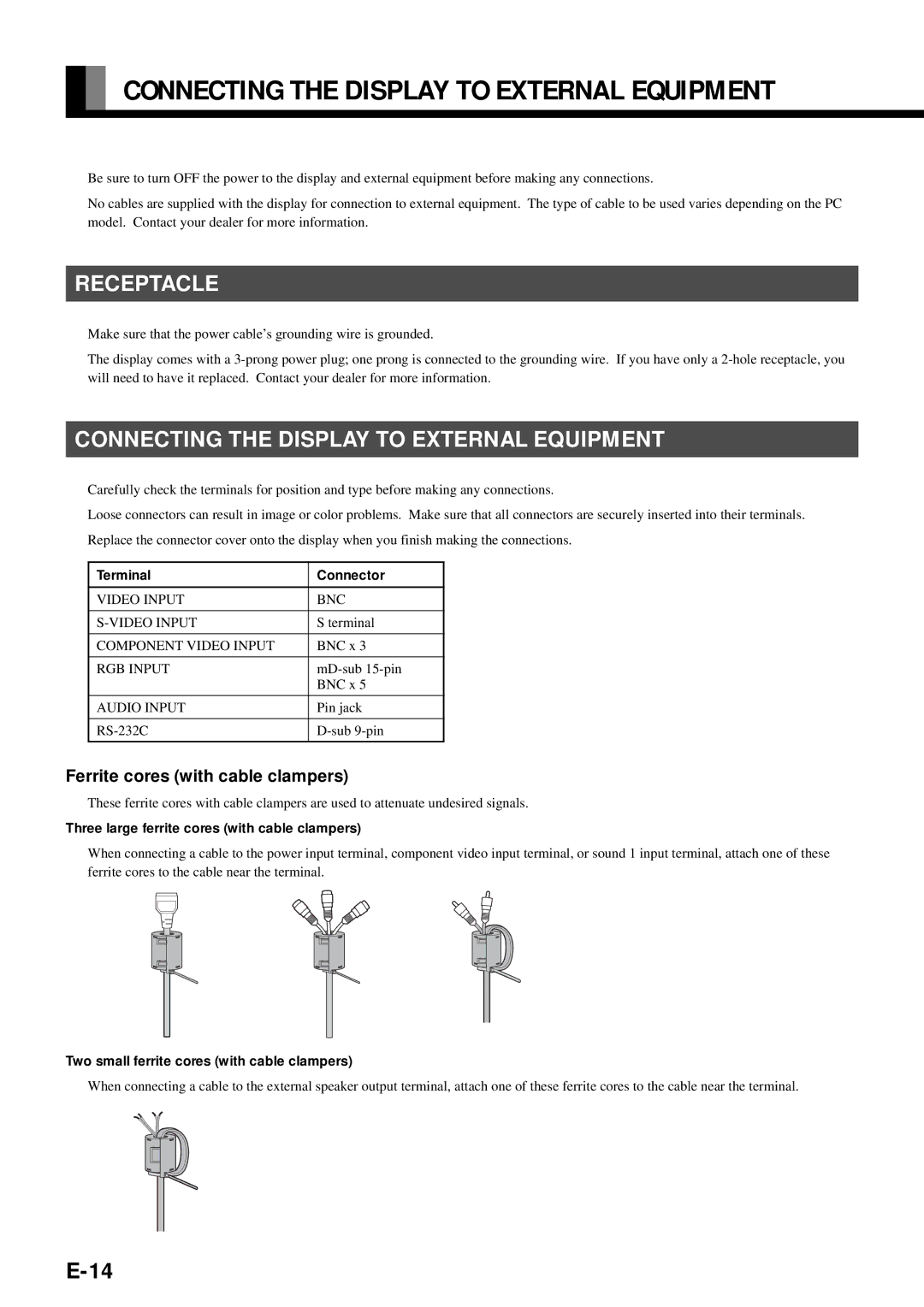
Ferrite cores (with cable clampers)
These ferrite cores with cable clampers are used to attenuate undesired signals.
Three large ferrite cores (with cable clampers)
When connecting a cable to the power input terminal, component video input terminal, or sound 1 input terminal, attach one of these ferrite cores to the cable near the terminal.
Two small ferrite cores (with cable clampers)
When connecting a cable to the external speaker output terminal, attach one of these ferrite cores to the cable near the terminal.