Video input terminal (VIDEO INPUT)
Connect this terminal to the video output terminal of your VCR or video disk player.
Sound2 input terminal (AUDIO2 INPUT)
Connect this terminal to the sound output terminal of your VCR, etc.
External speaker output terminal (EXT SP)
Connect this terminal to the optionally available speaker. (Use a speaker with 4 to 16 Ω.) When connecting cables L and R, attach a small ferrite core to each of the cables. (See P.
Power input terminal
Connect this terminal to the power cable supplied with the display.
Attach a large ferrite core to the power cable near the terminal. (See P.
Produces sound received through the sound input terminal.
Description of Input Terminals
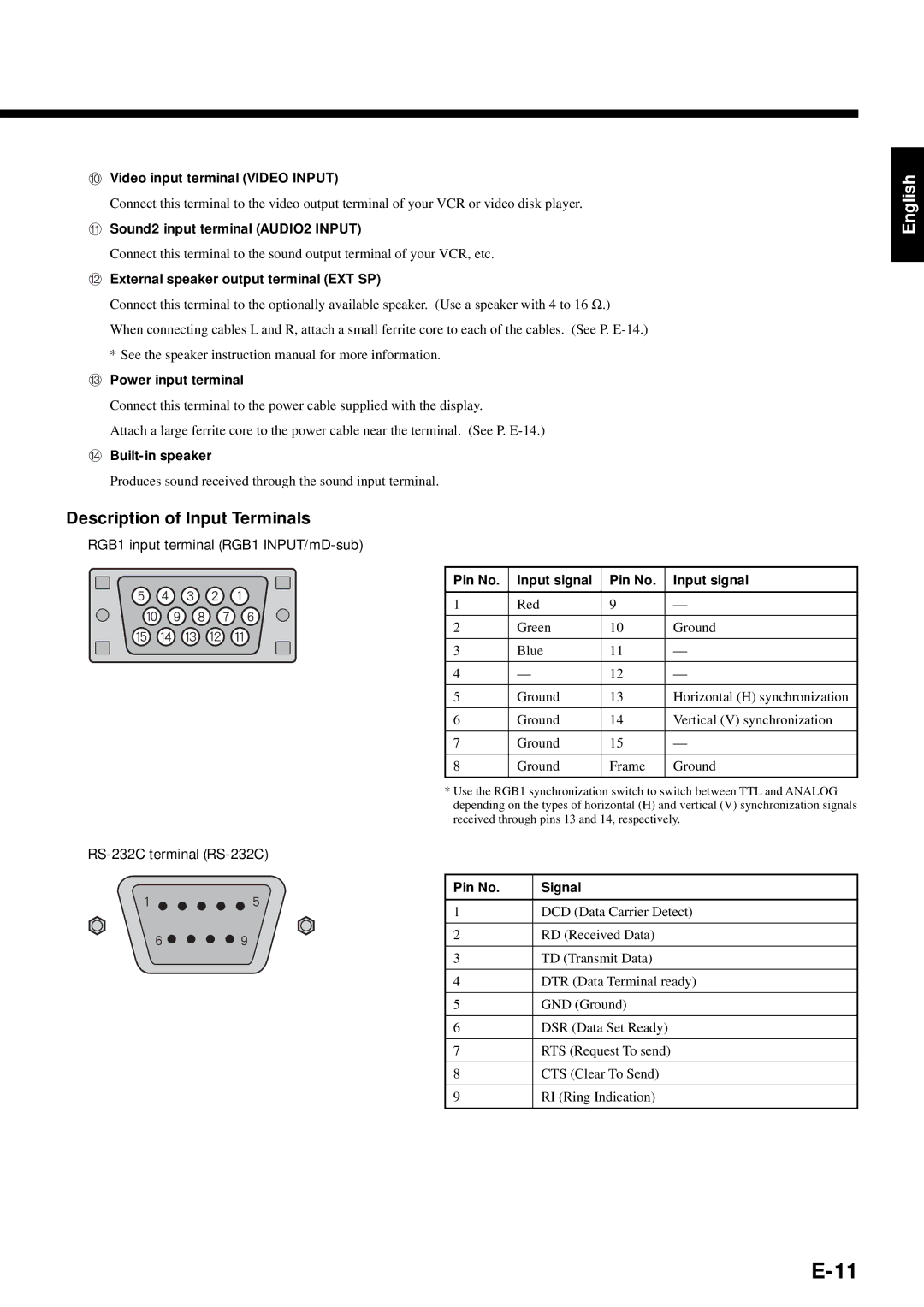
RGB1 input terminal (RGB1 INPUT/mD-sub)
Pin No. | Input signal | Pin No. | Input signal |
|
|
|
|
1 | Red | 9 | — |
|
|
|
|
2 | Green | 10 | Ground |
|
|
|
|
3 | Blue | 11 | — |
|
|
|
|
4 | — | 12 | — |
|
|
|
|
5 | Ground | 13 | Horizontal (H) synchronization |
|
|
|
|
6 | Ground | 14 | Vertical (V) synchronization |
|
|
|
|
7 | Ground | 15 | — |
|
|
|
|
8 | Ground | Frame | Ground |
|
|
|
|
*Use the RGB1 synchronization switch to switch between TTL and ANALOG depending on the types of horizontal (H) and vertical (V) synchronization signals received through pins 13 and 14, respectively.
RS-232C terminal (RS-232C)
Pin No. | Signal |
|
|
1 | DCD (Data Carrier Detect) |
|
|
2 | RD (Received Data) |
|
|
3 | TD (Transmit Data) |
|
|
4 | DTR (Data Terminal ready) |
|
|
5 | GND (Ground) |
|
|
6 | DSR (Data Set Ready) |
|
|
7 | RTS (Request To send) |
|
|
8 | CTS (Clear To Send) |
|
|
9 | RI (Ring Indication) |
|
|
English