3. INSTALLATION
3.3 Wiring
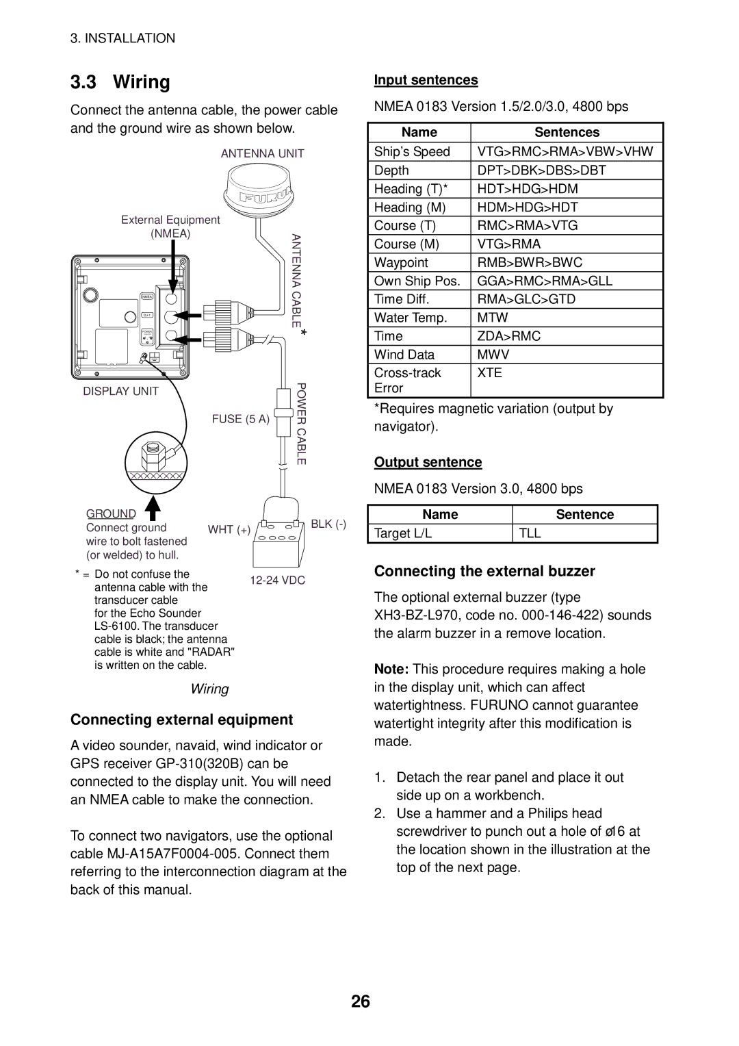
Connect the antenna cable, the power cable and the ground wire as shown below.
ANTENNA UNIT
External Equipment |
| |||
| (NMEA) |
| ANTENNA | |
|
|
| ||
| *CABLE | |||
NMEA |
|
| ||
|
| |||
POWER |
|
| ||
1 | 3 |
|
| |
| 2 |
|
| |
DISPLAY UNIT | FUSE (5 A) | POWER | ||
|
| |||
|
|
| CABLE | |
GROUND |
|
| BLK | |
Connect ground | WHT (+) | |||
| ||||
wire to bolt fastened (or welded) to hull.
* = Do not confuse the12-24 VDC antenna cable with the
transducer cable
for the Echo Sounder
Wiring
Connecting external equipment
A video sounder, navaid, wind indicator or GPS receiver
To connect two navigators, use the optional cable
Input sentences
NMEA 0183 Version 1.5/2.0/3.0, 4800 bps
Name | Sentences |
Ship’s Speed | VTG>RMC>RMA>VBW>VHW |
|
|
Depth | DPT>DBK>DBS>DBT |
|
|
Heading (T)* | HDT>HDG>HDM |
|
|
Heading (M) | HDM>HDG>HDT |
|
|
Course (T) | RMC>RMA>VTG |
|
|
Course (M) | VTG>RMA |
|
|
Waypoint | RMB>BWR>BWC |
|
|
Own Ship Pos. | GGA>RMC>RMA>GLL |
|
|
Time Diff. | RMA>GLC>GTD |
|
|
Water Temp. | MTW |
|
|
Time | ZDA>RMC |
|
|
Wind Data | MWV |
|
|
XTE | |
Error |
|
|
|
*Requires magnetic variation (output by navigator).
Output sentence
NMEA 0183 Version 3.0, 4800 bps
Name | Sentence |
Target L/L | TLL |
|
|
Connecting the external buzzer
The optional external buzzer (type
Note: This procedure requires making a hole in the display unit, which can affect watertightness. FURUNO cannot guarantee watertight integrity after this modification is made.
1.Detach the rear panel and place it out side up on a workbench.
2.Use a hammer and a Philips head screwdriver to punch out a hole of ø16 at the location shown in the illustration at the top of the next page.
26