Color LCD Searchlight Sonar
00080894802
Safety Instructions
TFT LCD
Table of Contents
Menu Operation
Foreword
Features
Usage Precautions
System Configuration
Viii
Control Description
Operational Overview
Remote controller
Remote Controller
Power on
Turning the Power On/Off
Power off
Lowering the transducer
Raising, Lowering the Transducer
Raising the transducer
Brilliance, panel dimmer dialog box
Adjusting Screen Brilliance, Panel Dimmer
Horizontal Expanded Horizontal
Selecting a Display
Basic Menu Operation
Adjusting the Gain
Dialog box for deleting track
Operational Overview
Horizontal Mode
Color
Typical Horizontal Mode Display
Selecting the Range
One-touch selection of 360 sector
Selecting Sector Width
Selecting the Tilt Angle
Selecting Train Center
Case2 Tilt angle 10 to
How to discriminate fish echoes from the bottom
Bottom echo and tilt angle
Case1 Tilt angle 30 to
Points to consider
Tilt angle for surface fish
Tilt angle and beam coverage
Suitable tilt angle
Finding Echo Position with the Cursor
Selecting the Training Speed
Inscribing the event marker
Event Marker
Deleting all event markers
Depth and Horizontal Range Markers
Suppressing bottom and surface reflections
Adjusting the Picture
Displaying weak echoes clearly
Suppressing bottom tail
To adjust TVG
Erasing weak echoes
Train center direction Position after expansion Remarks
Enlarging fish echoes expand horizontal display
Manual reserve mode
Setting target lock mode
Target Lock
To use the position mode
Position mode
Automatic echo tracking mode
Echo mode
Manual echo tracking mode
Horizontal menu description
Horizontal Menu Overview
LOG
Interpreting the Horizontal Display
How the horizontal mode picture is painted
Bottom echoes
Sample echo displays
Bottom
Fish schools
Wake
Sea surface reflections
Noise and interference
Sidelobe echo false echo
Horizontal/history display
Combination display examples
28 Horizontal/Video Plotter display
Horizontal/video plotter display
Press the key to display the horizontal/strata display
Horizontal/strata display
Flat bottom and strata display
Color bar for the strata display
31 Projection in fore direction and strata display
Projection in fore direction and strata display
Vertical FAN Mode
AFT
Typical Vertical Fan Mode Display
Range concept Default vertical fan mode range settings
Train indicator
One-touch selection of 180 sector
Selecting Display Sector
Automatic shifting of own ship position
Selecting Sector Center
NAV
11 How to inscribe, delete the event markers
12 Depth and horizontal range markers
13 Vert menu
14 Examples of proper and improper TVG
Suppressing noise and interference
Vertical menu description
Vertical Menu Overview
Interpreting the Vertical Fan Display
How the vertical fan mode picture is painted
Port-starboard picture bottom
When ship passes over fish schools
False echo
Display of net hauling
Train control
Horizontal/vertical fan display
Sector control
This page intentionally left blank
Event Menu
Echo Sounder Mode
Press the key to display the echo sounder picture
Typical Echo Sounder Display
Range concept Default echo sounder mode range settings
Selecting Tilt Angle
Train Direction
Selecting Picture Advance Speed
Measuring Range by Cursor
How to measure range with the cursor
How to inscribe, delete the event markers
Range marker
Range Marker
ES menu
A-scope display
Finding echo strength A-scope display
Echo sounder menu description
Echo Sounder Menu Overview
General use
This page intentionally left blank
COM1 Menu
Menu Operation
1 COM1 menu description
Displaying the COM2 menu
COM2 Menu
2 COM2 menu description
Selecting short-cut or preset
Short-cut Menu, Preset Menu
System menu
Activating custom mode
Preset key
Activating a short-cut key
Short-cut key
Vertical Search Function
SYS Menu
System Setting
System Setting 1 menu description
System Setting 1 menu
10 ETA marker
Default Setting YES
System Setting 2 menu description
Transducer being lowered
12 Factory Setting menu
13 Range-sonar mode menu
Sonar horizontal mode range settings
14 Range-ver mode menu
Vertical fan mode range settings
15 Range-E/S mode menu
Echo sounder mode range settings
16 Range-track mode menu
Track range settings
17 Color palette
Color palette
Loading backup data
System backup
Language
Demonstration mode
Transducer frequency adjustment
23 Default menu
Restoring all default settings
Preventive Maintenance
MAINTENANCE, Troubleshooting
Cleaning the Equipment
Lubrication
Hull Unit Maintenance
Manually raising, lowering transducer
Fuse Replacement
Transducer Maintenance
Symptom Check, Remedy
Troubleshooting
Message Meaning, Remedy Hull Unit
Error Messages
LED Exit
Diagnostics
Page
Test pattern
Test Pattern
Scope OFF, on
Menu Tree
From Previous
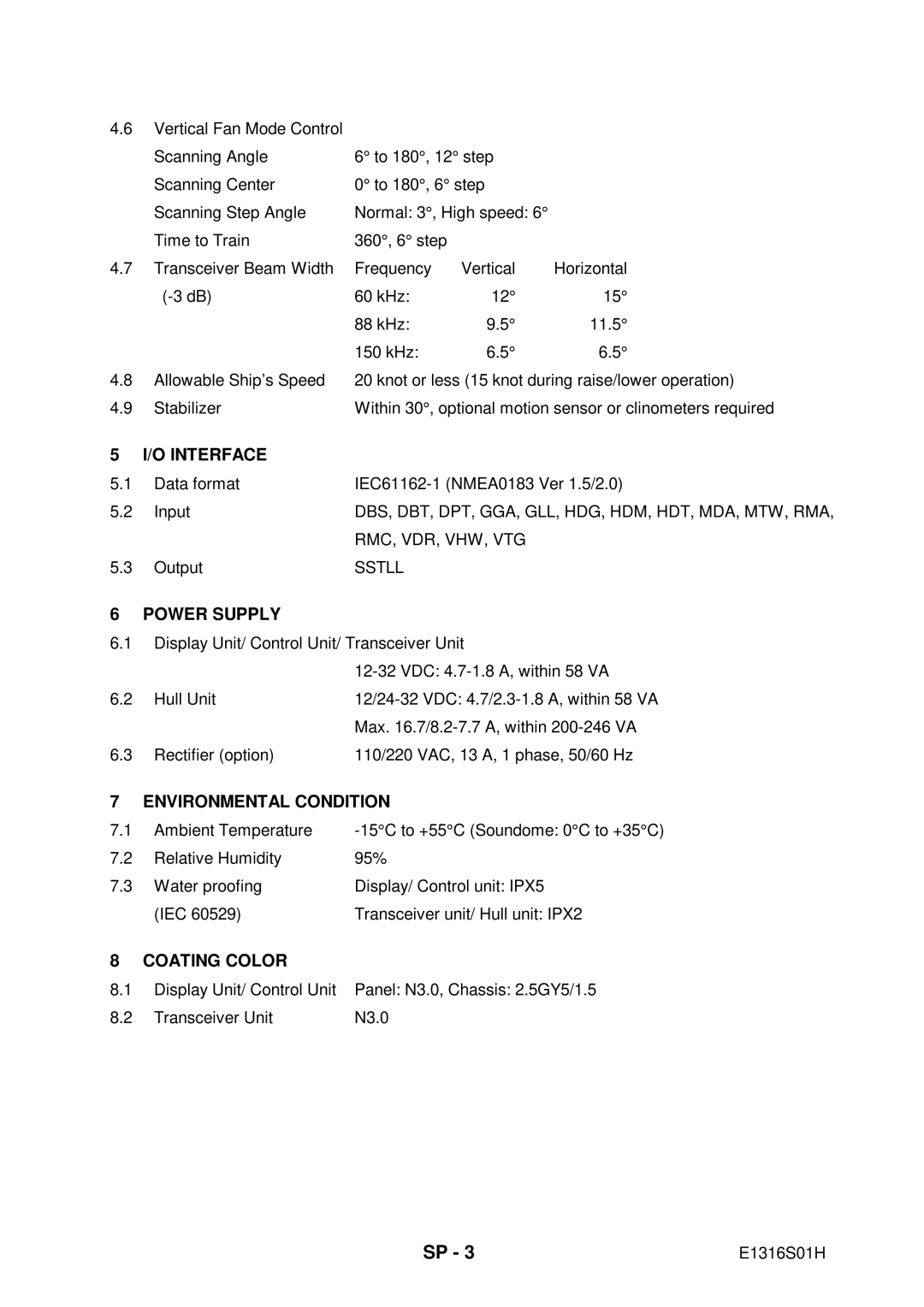
Specifications of 10.4 Inch Color LCD Searchlight Sonar
Transceiver Unit
Interface
This page is intentionally left blank
AGC
Index
IN-2
