CLUTTER: Low intensity echoes, often caused by sediments in water, are painted on the screen as a large number of random dots. The higher the number (setting) the weaker the echoes which are erased.
HORZ RANGE: You may choose the horizontal range expansion factor for the vertical scan picture, from x1 or x2. Note that this feature cannot be adjusted when the vertical search mode, activated by a function key, is turned on.
3.13 Interpreting the Vertical Fan Display
This section provides information necessary for interpreting the vertical fan display.
3.13.1 How the vertical fan mode picture is painted
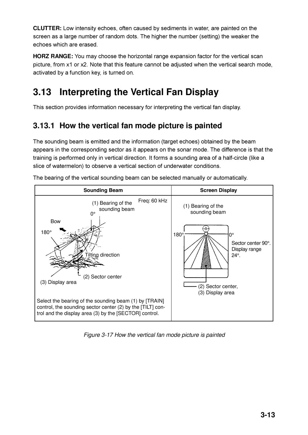
The sounding beam is emitted and the information (target echoes) obtained by the beam appears in the corresponding sector as it appears on the sonar mode. The difference is that the training is performed only in vertical direction. It forms a sounding area of a
The bearing of the vertical sounding beam can be selected manually or automatically.
| Sounding Beam |
| Screen Display | |||
|
|
|
|
|
|
|
| (1) Bearing of the | Freq: 60 kHz | (1) Bearing of the | |||
|
| |||||
| 0° sounding beam |
| ||||
|
| sounding beam | ||||
Bow |
|
|
|
|
|
|
180° |
| 180° |
|
|
|
|
|
|
|
|
| ||
|
|
|
|
| ||
| 0° | |||||
|
| |||||
|
|
|
|
|
| Sector center 90°. |
| Tilting direction |
|
|
|
| Display range |
|
| 24°. | ||||
(2) Sector center
(3) Display area
(2) Sector center,
(3) Display area
Select the bearing of the sounding beam (1) by [TRAIN] control, the sounding sector center (2) by the [TILT] con- trol and the display area (3) by the [SECTOR] control.
