4.4 Maintenance
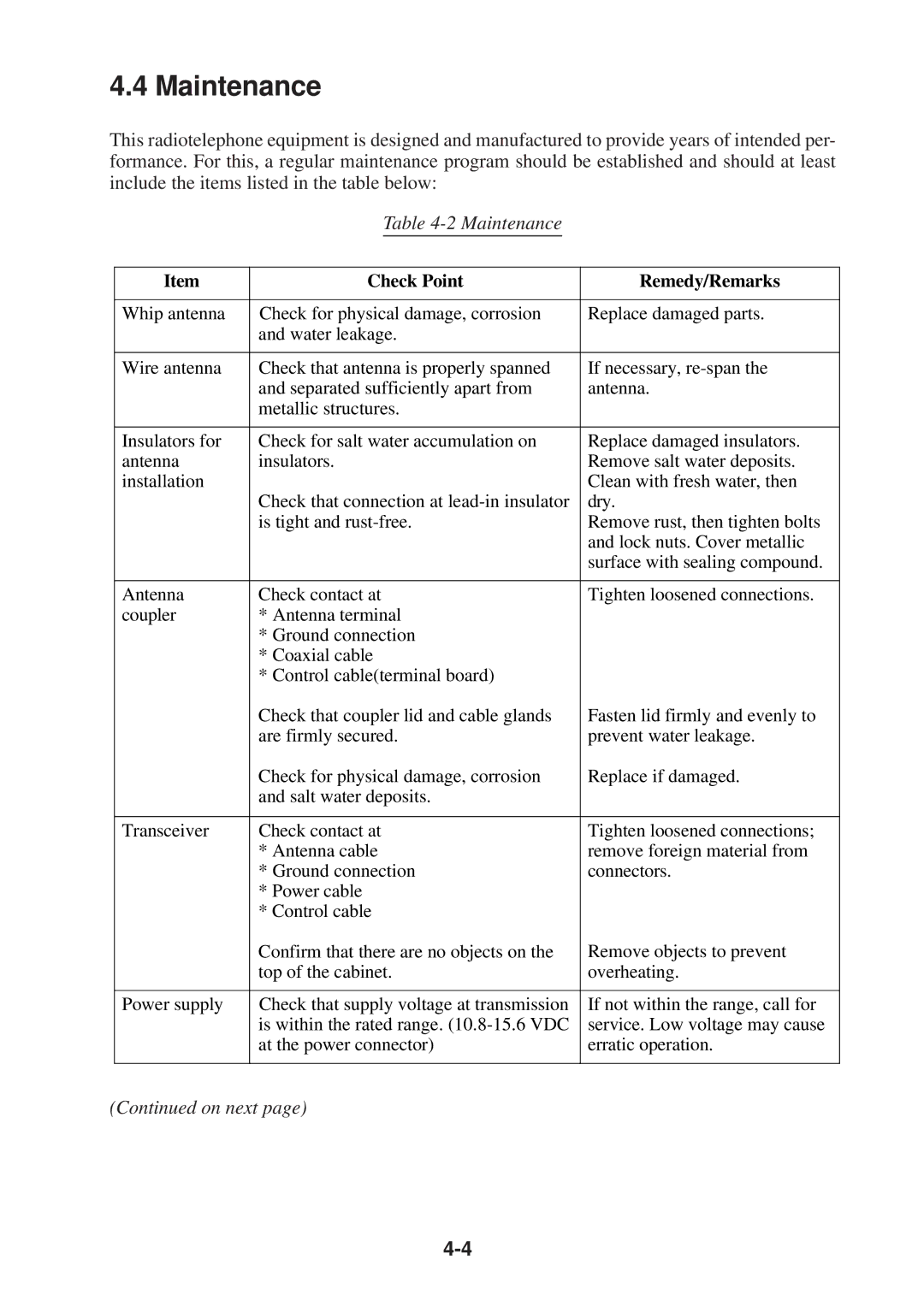
This radiotelephone equipment is designed and manufactured to provide years of intended per- formance. For this, a regular maintenance program should be established and should at least include the items listed in the table below:
Table 4-2 Maintenance
| Item |
| Check Point |
| Remedy/Remarks |
|
|
|
|
| |||
|
|
|
|
|
|
|
| Whip antenna |
| Check for physical damage, corrosion |
| Replace damaged parts. |
|
|
|
| and water leakage. |
|
|
|
|
|
|
|
|
|
|
| Wire antenna |
| Check that antenna is properly spanned |
| If necessary, |
|
|
|
| and separated sufficiently apart from |
| antenna. |
|
|
|
| metallic structures. |
|
|
|
|
|
|
|
|
|
|
| Insulators for |
| Check for salt water accumulation on |
| Replace damaged insulators. |
|
| antenna |
| insulators. |
| Remove salt water deposits. |
|
| installation |
|
|
| Clean with fresh water, then |
|
|
|
| Check that connection at |
| dry. |
|
|
|
| is tight and |
| Remove rust, then tighten bolts |
|
|
|
|
|
| and lock nuts. Cover metallic |
|
|
|
|
|
| surface with sealing compound. |
|
|
|
|
|
|
|
|
| Antenna |
| Check contact at |
| Tighten loosened connections. |
|
| coupler |
| * Antenna terminal |
|
|
|
|
|
| * Ground connection |
|
|
|
|
|
| * Coaxial cable |
|
|
|
|
|
| * Control cable(terminal board) |
|
|
|
|
|
| Check that coupler lid and cable glands |
| Fasten lid firmly and evenly to |
|
|
|
| are firmly secured. |
| prevent water leakage. |
|
|
|
| Check for physical damage, corrosion |
| Replace if damaged. |
|
|
|
| and salt water deposits. |
|
|
|
|
|
|
|
|
|
|
| Transceiver |
| Check contact at |
| Tighten loosened connections; |
|
|
|
| * Antenna cable |
| remove foreign material from |
|
|
|
| * Ground connection |
| connectors. |
|
|
|
| * Power cable |
|
|
|
|
|
| * Control cable |
|
|
|
|
|
| Confirm that there are no objects on the |
| Remove objects to prevent |
|
|
|
| top of the cabinet. |
| overheating. |
|
|
|
|
|
|
|
|
| Power supply |
| Check that supply voltage at transmission |
| If not within the range, call for |
|
|
|
| is within the rated range. |
| service. Low voltage may cause |
|
|
|
| at the power connector) |
| erratic operation. |
|
|
|
|
|
|
|
|
|
|
|
|
|
|
|
(Continued on next page)
